
User`s guide
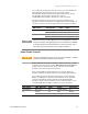
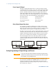


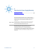


Table Of Contents
- Legal Notices
- Safety Notices
- In this Book
- Contents
- Quick Reference
- Installation
- Operating the Power Supply Locally
- Operating the Power Supply Remotely
- Language Reference
- SCPI Command Summary
- Calibration Commands
- Measure Commands
- Output Commands
- Source Commands
- [SOURce:]CURRent[:LEVel][:IMMediate][:AMPLitude]
|MIN|MAX [SOURce:]CURRent[:LEVel][:IMMediate][:AMPLitude]? [MIN|MAX] [SOURce:]CURRent[:LEVel]:TRIGgered[:AMPLitude] |MIN|MAX [SOURce:]CURRent[:LEVel]:TRIGgered[:AMPLitude]? [MIN|MAX] - [SOURce:]CURRent:PROTection:STATe ON|OFF [SOURce:]CURRent:PROTection:STATe?
- [SOURce:]VOLTage[:LEVel][:IMMediate][:AMPLitude]
|MIN|MAX [SOURce:]VOLTage[:LEVel][:IMMediate][:AMPLitude]? [MIN|MAX] [SOURce:]VOLTage[:LEVel]:TRIGgered[:AMPLitude] |MIN|MAX [SOURce:]VOLTage[:LEVel]:TRIGgered[:AMPLitude]? [MIN|MAX] - [SOURce:]VOLTage:LIMit:LOW
|MIN|MAX [SOURce:]VOLTage:LIMit:LOW? [MIN|MAX] - [SOURce:]VOLTage:PROTection:LEVel
|MIN|MAX [SOURce:]VOLTage:PROTection:LEVel? [MIN|MAX]
- [SOURce:]CURRent[:LEVel][:IMMediate][:AMPLitude]
- Status Commands
- STATus:PRESet
- STATus:OPERation[:EVENt]?
- STATus:OPERation:CONDition?
- STATus:OPERation:ENABle
STATus:OPERation:ENABle? - STATus:OPERation:NTR
STATus:OPERation:PTR STATus:OPERation:NTR? STATus:OPERation:PTR? - STATus:QUEStionable[:EVENt]?
- STATus:QUEStionable:CONDition?
- STATus:QUEStionable:ENABle
STATus:QUEStionable:ENABle? - STATus:QUEStionable:NTR
STATus:QUEStionable:PTR STATus:QUEStionable:NTR? STATus:QUEStionable:PTR? - *CLS
- *ESE *ESE?
- *ESR?
- *OPC *OPC?
- *SRE *SRE?
- *STB?
- *WAI
- System Commands
- Trigger Commands
- Programming Examples
- Specifications
- Verification and Calibration
- Verification
- Equipment Required
- Measurement Techniques
- Constant Voltage Tests
- Constant Current Tests
- Test Record Form – Agilent N5741A and N5761A
- Test Record Form – Agilent N5742A and N5762A
- Test Record Form – Agilent N5743A and N5763A
- Test Record Form – Agilent N5744A and N5764A
- Test Record Form – Agilent N5745A and N5765A
- Test Record Form – Agilent N5746A and N5766A
- Test Record Form – Agilent N5747A and N5767A
- Test Record Form – Agilent N5748A and N5768A
- Test Record Form – Agilent N5749A and N5769A
- Test Record Form – Agilent N5750A and N5770A
- Test Record Form – Agilent N5751A and N5771A
- Test Record Form – Agilent N5752A and N5772A
- Calibration
- Verification
- Service
- Compatibility
- Index
- Declaration of Conformity
3 Operating the Power Supply Locally
44 Series N5700 User’s Guide
• Set the programming sources to the desired levels and turn
the power supply on. Adjust the programming sources to
change the power supply output.
The analog control circuits let you set the output voltage and current
limit up to 5% over the model-rated maximum value. The power
supply will operate within the extended range, however it is not
recommended to operate the power supply over its voltage and
current rating, and performance in this region is not guaranteed.
SW1 switch 3 Voltage Programming
(J1 pin 9)
Current Programming
(J1 pin 10)
Down (default) 0 – 5 V 0 – 5 V
Up 0 – 10 V 0 – 10 V
Resistance Programming of Output Voltage and Current
Resistances of 0 - 5 kΩ or 0 - 10 kΩ can be selected to program the
output voltage and current limit from zero to full scale. Internal
current sources supply a 1mA current through the external resistors.
The voltage drop across the resistors is used as the programming
voltage for the power supply. To maintain the temperature stability
specification of the power supply, only use resistors that are stable
and low noise, with a temperature coefficient less than 50ppm.
Set the power supply to resistance programming as follows:
• Make sure that the power supply is turned off.
• Set SW1 setup switch 1 (for voltage) and 2 (for current) to
the UP position.
• Set SW1 setup switch 3 to select programming resistance
range according to the following table.
• Set SW1 setup switch 7 (for voltage) and 8 (for current) to
the Up position to enable resistance programming.
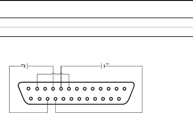
• Connect a short between J1 pin 8 and J1 pin 12 (see figure).
• Connect the programming resistors to the mating plug of J1
as shown in the following figure. A variable resistor can
control the output over its entire range, or a combination of
variable resistor and series/parallel resistors can control the
output over a restricted portion of its range.
1
14
13
25
10
12
8
9
23
22
+
+
CURRENT LIMIT
PROGRAMMING
OUTPUT VOLTAGE
PROGRAMMING