
User`s guide
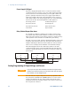


Table Of Contents
- Legal Notices
- Safety Notices
- In this Book
- Contents
- Quick Reference
- Installation
- Operating the Power Supply Locally
- Operating the Power Supply Remotely
- Language Reference
- SCPI Command Summary
- Calibration Commands
- Measure Commands
- Output Commands
- Source Commands
- [SOURce:]CURRent[:LEVel][:IMMediate][:AMPLitude]
|MIN|MAX [SOURce:]CURRent[:LEVel][:IMMediate][:AMPLitude]? [MIN|MAX] [SOURce:]CURRent[:LEVel]:TRIGgered[:AMPLitude] |MIN|MAX [SOURce:]CURRent[:LEVel]:TRIGgered[:AMPLitude]? [MIN|MAX] - [SOURce:]CURRent:PROTection:STATe ON|OFF [SOURce:]CURRent:PROTection:STATe?
- [SOURce:]VOLTage[:LEVel][:IMMediate][:AMPLitude]
|MIN|MAX [SOURce:]VOLTage[:LEVel][:IMMediate][:AMPLitude]? [MIN|MAX] [SOURce:]VOLTage[:LEVel]:TRIGgered[:AMPLitude] |MIN|MAX [SOURce:]VOLTage[:LEVel]:TRIGgered[:AMPLitude]? [MIN|MAX] - [SOURce:]VOLTage:LIMit:LOW
|MIN|MAX [SOURce:]VOLTage:LIMit:LOW? [MIN|MAX] - [SOURce:]VOLTage:PROTection:LEVel
|MIN|MAX [SOURce:]VOLTage:PROTection:LEVel? [MIN|MAX]
- [SOURce:]CURRent[:LEVel][:IMMediate][:AMPLitude]
- Status Commands
- STATus:PRESet
- STATus:OPERation[:EVENt]?
- STATus:OPERation:CONDition?
- STATus:OPERation:ENABle
STATus:OPERation:ENABle? - STATus:OPERation:NTR
STATus:OPERation:PTR STATus:OPERation:NTR? STATus:OPERation:PTR? - STATus:QUEStionable[:EVENt]?
- STATus:QUEStionable:CONDition?
- STATus:QUEStionable:ENABle
STATus:QUEStionable:ENABle? - STATus:QUEStionable:NTR
STATus:QUEStionable:PTR STATus:QUEStionable:NTR? STATus:QUEStionable:PTR? - *CLS
- *ESE *ESE?
- *ESR?
- *OPC *OPC?
- *SRE *SRE?
- *STB?
- *WAI
- System Commands
- Trigger Commands
- Programming Examples
- Specifications
- Verification and Calibration
- Verification
- Equipment Required
- Measurement Techniques
- Constant Voltage Tests
- Constant Current Tests
- Test Record Form – Agilent N5741A and N5761A
- Test Record Form – Agilent N5742A and N5762A
- Test Record Form – Agilent N5743A and N5763A
- Test Record Form – Agilent N5744A and N5764A
- Test Record Form – Agilent N5745A and N5765A
- Test Record Form – Agilent N5746A and N5766A
- Test Record Form – Agilent N5747A and N5767A
- Test Record Form – Agilent N5748A and N5768A
- Test Record Form – Agilent N5749A and N5769A
- Test Record Form – Agilent N5750A and N5770A
- Test Record Form – Agilent N5751A and N5771A
- Test Record Form – Agilent N5752A and N5772A
- Calibration
- Verification
- Service
- Compatibility
- Index
- Declaration of Conformity

Operating the Power Supply Locally 3
Series N5700 User’s Guide 43
The J1 connector also provides monitoring signals for the output
voltage and output current. The programming range and monitoring
signal range can be selected using the SW1 setup switch.
NOTE
With analog programming enabled, you cannot program the output voltage or
current using the front panel knobs or the remote interface. However, you can
read back output voltage or current from the front panel or the remote interface.
Analog Programming Control Terminals
J1 connector pin 8 accepts a TTL signal or an open/short contact
switch (referenced to pin 12) to select between Local or Analog
programming of the output voltage and current. This function is
enabled or disabled by SW1 setup switches 1 and 2.
J1 connector pin 21 is an open collector output that indicates if the
power supply is in Local mode or in Analog mode. To use this output,
connect a pull-up resistor to a voltage source of 30 VDC maximum.
Choose the pull-up resistor so that the sink current will be less than
5mA when the output is in low state.
SW1 switch 1 and 2 J1 pin 8
function
J1 pin 21
signal
Output voltage/
current control
Both Down (default) No effect Open Local
Either one, or both Up 0 or Short 0~0.6V Analog
1 or Open Open Local
Voltage Programming of Output Voltage and Current
CAUTION
To maintain the isolation of the power supply and prevent ground loops, use an
isolated programming source when operating the unit using analog programming.
Voltage programming sources of 0 - 5 V or 0 - 10 V can be used to
program the output voltage and current limit from zero to full scale.
Set the power supply to analog voltage programming as follows:
• Make sure that the power supply is turned off.
• Set SW1 setup switch 1 (for voltage) and 2 (for current) to
the Up position.
• Set SW1 setup switch 3 to select programming voltage range
according to the following table.
• Make sure that SW1 setup switches 7 and 8 are set Down.
• Connect a short between J1 pin 8 and J1 pin 12 (see figure).
• Connect the programming source to the mating plug of J1 as
shown in the following figure. Observe the correct polarity
for the voltage source.