
User`s guide


Table Of Contents
- Legal Notices
- Safety Notices
- In this Book
- Contents
- Quick Reference
- Installation
- Operating the Power Supply Locally
- Operating the Power Supply Remotely
- Language Reference
- SCPI Command Summary
- Calibration Commands
- Measure Commands
- Output Commands
- Source Commands
- [SOURce:]CURRent[:LEVel][:IMMediate][:AMPLitude]
|MIN|MAX [SOURce:]CURRent[:LEVel][:IMMediate][:AMPLitude]? [MIN|MAX] [SOURce:]CURRent[:LEVel]:TRIGgered[:AMPLitude] |MIN|MAX [SOURce:]CURRent[:LEVel]:TRIGgered[:AMPLitude]? [MIN|MAX] - [SOURce:]CURRent:PROTection:STATe ON|OFF [SOURce:]CURRent:PROTection:STATe?
- [SOURce:]VOLTage[:LEVel][:IMMediate][:AMPLitude]
|MIN|MAX [SOURce:]VOLTage[:LEVel][:IMMediate][:AMPLitude]? [MIN|MAX] [SOURce:]VOLTage[:LEVel]:TRIGgered[:AMPLitude] |MIN|MAX [SOURce:]VOLTage[:LEVel]:TRIGgered[:AMPLitude]? [MIN|MAX] - [SOURce:]VOLTage:LIMit:LOW
|MIN|MAX [SOURce:]VOLTage:LIMit:LOW? [MIN|MAX] - [SOURce:]VOLTage:PROTection:LEVel
|MIN|MAX [SOURce:]VOLTage:PROTection:LEVel? [MIN|MAX]
- [SOURce:]CURRent[:LEVel][:IMMediate][:AMPLitude]
- Status Commands
- STATus:PRESet
- STATus:OPERation[:EVENt]?
- STATus:OPERation:CONDition?
- STATus:OPERation:ENABle
STATus:OPERation:ENABle? - STATus:OPERation:NTR
STATus:OPERation:PTR STATus:OPERation:NTR? STATus:OPERation:PTR? - STATus:QUEStionable[:EVENt]?
- STATus:QUEStionable:CONDition?
- STATus:QUEStionable:ENABle
STATus:QUEStionable:ENABle? - STATus:QUEStionable:NTR
STATus:QUEStionable:PTR STATus:QUEStionable:NTR? STATus:QUEStionable:PTR? - *CLS
- *ESE *ESE?
- *ESR?
- *OPC *OPC?
- *SRE *SRE?
- *STB?
- *WAI
- System Commands
- Trigger Commands
- Programming Examples
- Specifications
- Verification and Calibration
- Verification
- Equipment Required
- Measurement Techniques
- Constant Voltage Tests
- Constant Current Tests
- Test Record Form – Agilent N5741A and N5761A
- Test Record Form – Agilent N5742A and N5762A
- Test Record Form – Agilent N5743A and N5763A
- Test Record Form – Agilent N5744A and N5764A
- Test Record Form – Agilent N5745A and N5765A
- Test Record Form – Agilent N5746A and N5766A
- Test Record Form – Agilent N5747A and N5767A
- Test Record Form – Agilent N5748A and N5768A
- Test Record Form – Agilent N5749A and N5769A
- Test Record Form – Agilent N5750A and N5770A
- Test Record Form – Agilent N5751A and N5771A
- Test Record Form – Agilent N5752A and N5772A
- Calibration
- Verification
- Service
- Compatibility
- Index
- Declaration of Conformity
2 Installation
32 Series N5700 User’s Guide
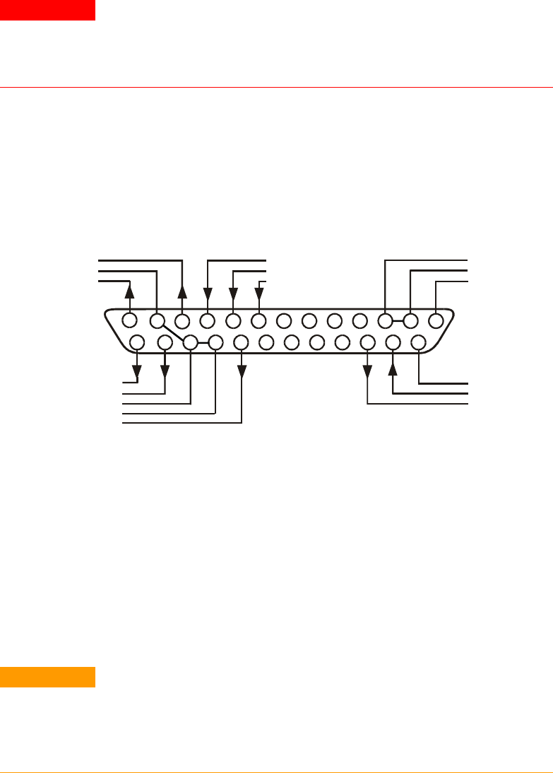
J1 Connector Connections
WARNING
SHOCK HAZARD There is a potential shock hazard at the J1 connector when
using a power supply with a rated output greater than 40V. Ensure that the
load wiring insulation rating is greater than or equal to the maximum output
voltage of the power supply.
External programming and monitoring signal are located on the J1
connector. The power supply is shipped with a mating plug that
makes it easy for you to make your wire connections. It is essential to
use this plastic-body plug to conform to safety agency requirements.
If a shield is required for the J1 wires, connect the shield to the
ground screw located on the power supply chassis.
Refer to the following figure for the pin assignments. A description of
the pins is given in chapter 1.
The mating plug specifications for the J1 connector are as follows:
Mating Plug:
AMP part number 745211-2
Wire Size:
AWG 26 to AWG 22
Extraction tool:
AMP part number 91232-1 or equivalent
Manual pistol grip tool: Handle: AMP p/n 58074-1
Head: AMP p/n 58063-1
CAUTION
Pins 12, 22 and 23 of J1 are connected internally to the negative sense (-S)
potential of the power supply. Do not attempt to bias any of these pins relative
to the negative output terminal. Use an isolated, ungrounded, programming
source to prevent ground loops and to maintain the isolation of the power
supply when programming from J1.
Chapter 3 describes how to configure the J1 connector when using it
to program the output voltage and current.
14151617
18
19
20
21
22
232425
12
3
45
6
7
8
10
11
12
13
9
Current Monitor
Current Prog. Return
Voltage Prog. Return
Local / Analog State
Chassis Common
Enable +
Voltage Monitor
Common (-S)
CV / CC
Current Program
Voltage Program
Local / Analog
Parallel Enable --
Shut Off
Power Supply OK
Chassis Common
Pins on this side are isolated
from output terminals and are
referenced to chassis ground.
Pins on this side are
referenced to the negative
sense (-S) terminal.