
User`s guide
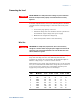
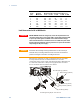
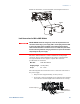

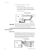
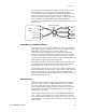

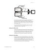
Table Of Contents
- Legal Notices
- Safety Notices
- In this Book
- Contents
- Quick Reference
- Installation
- Operating the Power Supply Locally
- Operating the Power Supply Remotely
- Language Reference
- SCPI Command Summary
- Calibration Commands
- Measure Commands
- Output Commands
- Source Commands
- [SOURce:]CURRent[:LEVel][:IMMediate][:AMPLitude]
|MIN|MAX [SOURce:]CURRent[:LEVel][:IMMediate][:AMPLitude]? [MIN|MAX] [SOURce:]CURRent[:LEVel]:TRIGgered[:AMPLitude] |MIN|MAX [SOURce:]CURRent[:LEVel]:TRIGgered[:AMPLitude]? [MIN|MAX] - [SOURce:]CURRent:PROTection:STATe ON|OFF [SOURce:]CURRent:PROTection:STATe?
- [SOURce:]VOLTage[:LEVel][:IMMediate][:AMPLitude]
|MIN|MAX [SOURce:]VOLTage[:LEVel][:IMMediate][:AMPLitude]? [MIN|MAX] [SOURce:]VOLTage[:LEVel]:TRIGgered[:AMPLitude] |MIN|MAX [SOURce:]VOLTage[:LEVel]:TRIGgered[:AMPLitude]? [MIN|MAX] - [SOURce:]VOLTage:LIMit:LOW
|MIN|MAX [SOURce:]VOLTage:LIMit:LOW? [MIN|MAX] - [SOURce:]VOLTage:PROTection:LEVel
|MIN|MAX [SOURce:]VOLTage:PROTection:LEVel? [MIN|MAX]
- [SOURce:]CURRent[:LEVel][:IMMediate][:AMPLitude]
- Status Commands
- STATus:PRESet
- STATus:OPERation[:EVENt]?
- STATus:OPERation:CONDition?
- STATus:OPERation:ENABle
STATus:OPERation:ENABle? - STATus:OPERation:NTR
STATus:OPERation:PTR STATus:OPERation:NTR? STATus:OPERation:PTR? - STATus:QUEStionable[:EVENt]?
- STATus:QUEStionable:CONDition?
- STATus:QUEStionable:ENABle
STATus:QUEStionable:ENABle? - STATus:QUEStionable:NTR
STATus:QUEStionable:PTR STATus:QUEStionable:NTR? STATus:QUEStionable:PTR? - *CLS
- *ESE *ESE?
- *ESR?
- *OPC *OPC?
- *SRE *SRE?
- *STB?
- *WAI
- System Commands
- Trigger Commands
- Programming Examples
- Specifications
- Verification and Calibration
- Verification
- Equipment Required
- Measurement Techniques
- Constant Voltage Tests
- Constant Current Tests
- Test Record Form – Agilent N5741A and N5761A
- Test Record Form – Agilent N5742A and N5762A
- Test Record Form – Agilent N5743A and N5763A
- Test Record Form – Agilent N5744A and N5764A
- Test Record Form – Agilent N5745A and N5765A
- Test Record Form – Agilent N5746A and N5766A
- Test Record Form – Agilent N5747A and N5767A
- Test Record Form – Agilent N5748A and N5768A
- Test Record Form – Agilent N5749A and N5769A
- Test Record Form – Agilent N5750A and N5770A
- Test Record Form – Agilent N5751A and N5771A
- Test Record Form – Agilent N5752A and N5772A
- Calibration
- Verification
- Service
- Compatibility
- Index
- Declaration of Conformity

2 Installation
30 Series N5700 User’s Guide
Setting the Over-Voltage Protection
The master unit OVP should be programmed to the desired OVP level.
The OVP of the slave units should be programmed to a higher value
than the master. When the master unit shuts down, it programs the
slave unit to zero output voltage. If a slave unit shuts down when its
OVP is set lower than the master output voltage, only that unit shuts
down and the remaining slave units will supply all the load current.
Setting the Over-Current Protection
Over-current protection, if desired, may only be used with the master
unit. When the master unit shuts down, it programs the slave units to
zero output voltage.
Series Connections
WARNING
SHOCK HAZARD For models up to 60VDC rated output, no point shall be more
than +/-60VDC above/below chassis ground. For models > 60VDC rated
output, no point shall be more than +/-600VDC above/below chassis ground.
There is also a potential shock hazard at the IEEE/LAN/USB ports when
using power supplies with rated or combined voltages > 400VDC with the
positive output of the power supplies grounded. Do not connect the positive
output to ground when using the IEEE/LAN/USB under the above conditions.
CAUTION
Only power supplies that have identical voltage and current ratings can be
connected in series.
Two units of the same voltage and current rating can be connected in
series to provide up to two times the output voltage capability.
Because the current is the same through each element in a series
circuit, outputs connected in series must have equivalent current
ratings. Otherwise, the higher rated output could potentially damage
the lower rated output by forcing excessive current through it under
certain load conditions. Refer to the following figures for typical
series connections using either local or remote sensing.
It is recommended that diodes be connected in parallel with each
output to prevent reverse voltage during start up sequence or in case
one unit shuts down. Each diode should be rated to at least the rated
output voltage and output current of the power supply.