
User`s guide
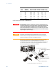
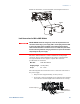

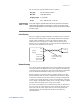
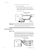
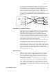

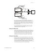
Table Of Contents
- Legal Notices
- Safety Notices
- In this Book
- Contents
- Quick Reference
- Installation
- Operating the Power Supply Locally
- Operating the Power Supply Remotely
- Language Reference
- SCPI Command Summary
- Calibration Commands
- Measure Commands
- Output Commands
- Source Commands
- [SOURce:]CURRent[:LEVel][:IMMediate][:AMPLitude]
|MIN|MAX [SOURce:]CURRent[:LEVel][:IMMediate][:AMPLitude]? [MIN|MAX] [SOURce:]CURRent[:LEVel]:TRIGgered[:AMPLitude] |MIN|MAX [SOURce:]CURRent[:LEVel]:TRIGgered[:AMPLitude]? [MIN|MAX] - [SOURce:]CURRent:PROTection:STATe ON|OFF [SOURce:]CURRent:PROTection:STATe?
- [SOURce:]VOLTage[:LEVel][:IMMediate][:AMPLitude]
|MIN|MAX [SOURce:]VOLTage[:LEVel][:IMMediate][:AMPLitude]? [MIN|MAX] [SOURce:]VOLTage[:LEVel]:TRIGgered[:AMPLitude] |MIN|MAX [SOURce:]VOLTage[:LEVel]:TRIGgered[:AMPLitude]? [MIN|MAX] - [SOURce:]VOLTage:LIMit:LOW
|MIN|MAX [SOURce:]VOLTage:LIMit:LOW? [MIN|MAX] - [SOURce:]VOLTage:PROTection:LEVel
|MIN|MAX [SOURce:]VOLTage:PROTection:LEVel? [MIN|MAX]
- [SOURce:]CURRent[:LEVel][:IMMediate][:AMPLitude]
- Status Commands
- STATus:PRESet
- STATus:OPERation[:EVENt]?
- STATus:OPERation:CONDition?
- STATus:OPERation:ENABle
STATus:OPERation:ENABle? - STATus:OPERation:NTR
STATus:OPERation:PTR STATus:OPERation:NTR? STATus:OPERation:PTR? - STATus:QUEStionable[:EVENt]?
- STATus:QUEStionable:CONDition?
- STATus:QUEStionable:ENABle
STATus:QUEStionable:ENABle? - STATus:QUEStionable:NTR
STATus:QUEStionable:PTR STATus:QUEStionable:NTR? STATus:QUEStionable:PTR? - *CLS
- *ESE *ESE?
- *ESR?
- *OPC *OPC?
- *SRE *SRE?
- *STB?
- *WAI
- System Commands
- Trigger Commands
- Programming Examples
- Specifications
- Verification and Calibration
- Verification
- Equipment Required
- Measurement Techniques
- Constant Voltage Tests
- Constant Current Tests
- Test Record Form – Agilent N5741A and N5761A
- Test Record Form – Agilent N5742A and N5762A
- Test Record Form – Agilent N5743A and N5763A
- Test Record Form – Agilent N5744A and N5764A
- Test Record Form – Agilent N5745A and N5765A
- Test Record Form – Agilent N5746A and N5766A
- Test Record Form – Agilent N5747A and N5767A
- Test Record Form – Agilent N5748A and N5768A
- Test Record Form – Agilent N5749A and N5769A
- Test Record Form – Agilent N5750A and N5770A
- Test Record Form – Agilent N5751A and N5771A
- Test Record Form – Agilent N5752A and N5772A
- Calibration
- Verification
- Service
- Compatibility
- Index
- Declaration of Conformity
2 Installation
24 Series N5700 User’s Guide
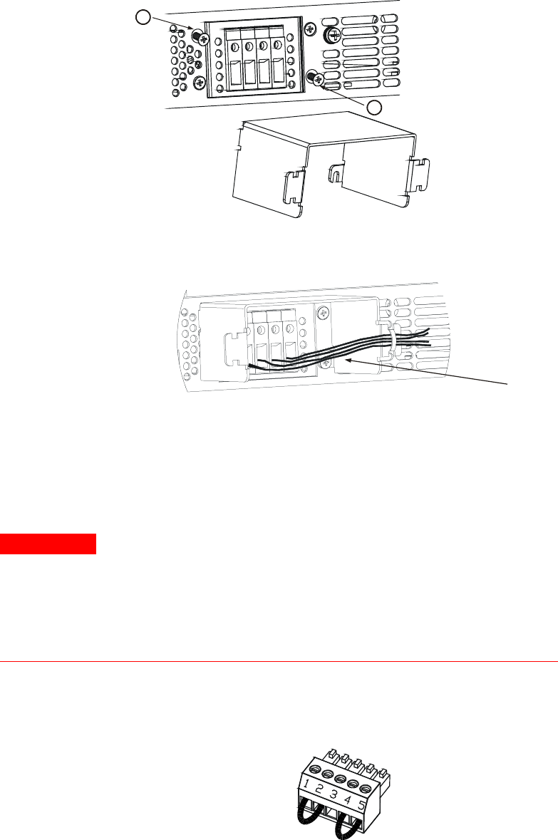
• Loosen the two chassis screws marked A halfway.
• Assemble the protective shield to the chassis and tighten the
two screws to fix the shield to the chassis. Screw tightening
torque: 4.8-5.3 in-lb
• Tighten the wires to one of the shield sides using tie-wrap or
equivalent. Refer to the following figure.
• Ensure that the wire length inside the shield is long enough
to provide proper strain relief.
Output Voltage Sensing
WARNING
SHOCK HAZARD There is a potential shock hazard at the sense connector
when using a power supply with a rated output greater than 40V. Ensure that
the local sense and remote sense wiring insulation rating is greater than or
equal to the maximum output voltage of the power supply. Ensure that the
connections at the load end are shielded to prevent accidental contact with
hazardous voltages.
Local and remote sense connections are made at the J2 connector.
The connector has a removable plug that makes it easy for you to
make your wire connections. Refer to the following figure for the
terminal assignments.
A
A
Load
wire
s
1 Remote sense (+)
2 Local sense (+)
3 Not connected
4 Local sense (-)
5 Remote sense (-)