
User`s guide
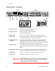
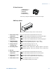
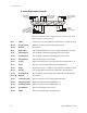


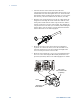
Table Of Contents
- Legal Notices
- Safety Notices
- In this Book
- Contents
- Quick Reference
- Installation
- Operating the Power Supply Locally
- Operating the Power Supply Remotely
- Language Reference
- SCPI Command Summary
- Calibration Commands
- Measure Commands
- Output Commands
- Source Commands
- [SOURce:]CURRent[:LEVel][:IMMediate][:AMPLitude]
|MIN|MAX [SOURce:]CURRent[:LEVel][:IMMediate][:AMPLitude]? [MIN|MAX] [SOURce:]CURRent[:LEVel]:TRIGgered[:AMPLitude] |MIN|MAX [SOURce:]CURRent[:LEVel]:TRIGgered[:AMPLitude]? [MIN|MAX] - [SOURce:]CURRent:PROTection:STATe ON|OFF [SOURce:]CURRent:PROTection:STATe?
- [SOURce:]VOLTage[:LEVel][:IMMediate][:AMPLitude]
|MIN|MAX [SOURce:]VOLTage[:LEVel][:IMMediate][:AMPLitude]? [MIN|MAX] [SOURce:]VOLTage[:LEVel]:TRIGgered[:AMPLitude] |MIN|MAX [SOURce:]VOLTage[:LEVel]:TRIGgered[:AMPLitude]? [MIN|MAX] - [SOURce:]VOLTage:LIMit:LOW
|MIN|MAX [SOURce:]VOLTage:LIMit:LOW? [MIN|MAX] - [SOURce:]VOLTage:PROTection:LEVel
|MIN|MAX [SOURce:]VOLTage:PROTection:LEVel? [MIN|MAX]
- [SOURce:]CURRent[:LEVel][:IMMediate][:AMPLitude]
- Status Commands
- STATus:PRESet
- STATus:OPERation[:EVENt]?
- STATus:OPERation:CONDition?
- STATus:OPERation:ENABle
STATus:OPERation:ENABle? - STATus:OPERation:NTR
STATus:OPERation:PTR STATus:OPERation:NTR? STATus:OPERation:PTR? - STATus:QUEStionable[:EVENt]?
- STATus:QUEStionable:CONDition?
- STATus:QUEStionable:ENABle
STATus:QUEStionable:ENABle? - STATus:QUEStionable:NTR
STATus:QUEStionable:PTR STATus:QUEStionable:NTR? STATus:QUEStionable:PTR? - *CLS
- *ESE *ESE?
- *ESR?
- *OPC *OPC?
- *SRE *SRE?
- *STB?
- *WAI
- System Commands
- Trigger Commands
- Programming Examples
- Specifications
- Verification and Calibration
- Verification
- Equipment Required
- Measurement Techniques
- Constant Voltage Tests
- Constant Current Tests
- Test Record Form – Agilent N5741A and N5761A
- Test Record Form – Agilent N5742A and N5762A
- Test Record Form – Agilent N5743A and N5763A
- Test Record Form – Agilent N5744A and N5764A
- Test Record Form – Agilent N5745A and N5765A
- Test Record Form – Agilent N5746A and N5766A
- Test Record Form – Agilent N5747A and N5767A
- Test Record Form – Agilent N5748A and N5768A
- Test Record Form – Agilent N5749A and N5769A
- Test Record Form – Agilent N5750A and N5770A
- Test Record Form – Agilent N5751A and N5771A
- Test Record Form – Agilent N5752A and N5772A
- Calibration
- Verification
- Service
- Compatibility
- Index
- Declaration of Conformity

Installation 2
Series N5700 User’s Guide 19
Connecting the Line Cord
WARNING
SHOCK HAZARD The power cord provides a chassis ground through a third
conductor. Be certain that your power outlet is of the three-conductor type
with the correct pin connected to earth ground.
FIRE HAZARD Use only the power cord that was supplied with your
instrument. Using other types of power cords may cause overheating of the
power cord, resulting in fire.
NOTE
The detachable power cord may be used as an emergency disconnecting
device. Removing the power cord will disconnect ac input power to the unit.
The AC input on the back of your unit is a universal AC input. It
accepts line voltages in the range of 85 VAC to 265 VAC. The
frequency range is 47 Hz to 63 Hz.
The input current requirement of 750W units is 10.5A @ 100 VAC
nominal and 5A @ 200 VAC nominal. The current requirement of
1500W units is 21A @ 100 VAC nominal and 11A @ 200 VAC nominal.
Input Connections for 750W units
Connect the power cord to the IEC 320 connector on the rear of the
unit. The IEC connector provides the safety ground connection when
the AC cord is plugged into a grounded AC receptacle.
If the wrong power cord was shipped with your unit, contact your
nearest Agilent Sales and Service Office.
Input Connections for 1500W units
CAUTION
Connection of this power supply to an AC power source should be made by a
qualified electrician or other qualified personnel.
The AC input connector is a 3-terminal wire clamp located on the
rear panel. Use suitable wires and tightening torque as follows:
• Wire diameter: 12 AWG or 10 AWG
• Tightening torque: 6.5 - 7.0 in-lb
Connect the cable to the AC input connector as follows:
• Strip the outside insulation of the AC cable approximately 10
cm (4 in). Trim the wires so that the ground wire is 10 mm
(0.4 in) longer than the other wires. Strip 14 mm (0.55 in) at
the end of each of the wires.