
User`s guide

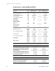
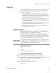

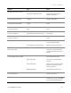


Table Of Contents
- Legal Notices
- Safety Notices
- In this Book
- Contents
- Quick Reference
- Installation
- Operating the Power Supply Locally
- Operating the Power Supply Remotely
- Language Reference
- SCPI Command Summary
- Calibration Commands
- Measure Commands
- Output Commands
- Source Commands
- [SOURce:]CURRent[:LEVel][:IMMediate][:AMPLitude]
|MIN|MAX [SOURce:]CURRent[:LEVel][:IMMediate][:AMPLitude]? [MIN|MAX] [SOURce:]CURRent[:LEVel]:TRIGgered[:AMPLitude] |MIN|MAX [SOURce:]CURRent[:LEVel]:TRIGgered[:AMPLitude]? [MIN|MAX] - [SOURce:]CURRent:PROTection:STATe ON|OFF [SOURce:]CURRent:PROTection:STATe?
- [SOURce:]VOLTage[:LEVel][:IMMediate][:AMPLitude]
|MIN|MAX [SOURce:]VOLTage[:LEVel][:IMMediate][:AMPLitude]? [MIN|MAX] [SOURce:]VOLTage[:LEVel]:TRIGgered[:AMPLitude] |MIN|MAX [SOURce:]VOLTage[:LEVel]:TRIGgered[:AMPLitude]? [MIN|MAX] - [SOURce:]VOLTage:LIMit:LOW
|MIN|MAX [SOURce:]VOLTage:LIMit:LOW? [MIN|MAX] - [SOURce:]VOLTage:PROTection:LEVel
|MIN|MAX [SOURce:]VOLTage:PROTection:LEVel? [MIN|MAX]
- [SOURce:]CURRent[:LEVel][:IMMediate][:AMPLitude]
- Status Commands
- STATus:PRESet
- STATus:OPERation[:EVENt]?
- STATus:OPERation:CONDition?
- STATus:OPERation:ENABle
STATus:OPERation:ENABle? - STATus:OPERation:NTR
STATus:OPERation:PTR STATus:OPERation:NTR? STATus:OPERation:PTR? - STATus:QUEStionable[:EVENt]?
- STATus:QUEStionable:CONDition?
- STATus:QUEStionable:ENABle
STATus:QUEStionable:ENABle? - STATus:QUEStionable:NTR
STATus:QUEStionable:PTR STATus:QUEStionable:NTR? STATus:QUEStionable:PTR? - *CLS
- *ESE *ESE?
- *ESR?
- *OPC *OPC?
- *SRE *SRE?
- *STB?
- *WAI
- System Commands
- Trigger Commands
- Programming Examples
- Specifications
- Verification and Calibration
- Verification
- Equipment Required
- Measurement Techniques
- Constant Voltage Tests
- Constant Current Tests
- Test Record Form – Agilent N5741A and N5761A
- Test Record Form – Agilent N5742A and N5762A
- Test Record Form – Agilent N5743A and N5763A
- Test Record Form – Agilent N5744A and N5764A
- Test Record Form – Agilent N5745A and N5765A
- Test Record Form – Agilent N5746A and N5766A
- Test Record Form – Agilent N5747A and N5767A
- Test Record Form – Agilent N5748A and N5768A
- Test Record Form – Agilent N5749A and N5769A
- Test Record Form – Agilent N5750A and N5770A
- Test Record Form – Agilent N5751A and N5771A
- Test Record Form – Agilent N5752A and N5772A
- Calibration
- Verification
- Service
- Compatibility
- Index
- Declaration of Conformity

Service Appendix C
Series N5700 User’s Guide 117
Symptom Check Action
No output.
All displays and indicators are blank.
Is the AC power cord defective?
Is the AC input voltage within range?
Check continuity. Replace if necessary.
Check AC input voltage. Connect to
appropriate voltage source.
Output is present momentarily, but shuts
off quickly. Display indicates AC.
Does the AC source voltage sag when a load
is applied?
Check AC input voltage. Connect to
appropriate voltage source.
Output is present momentarily, but shuts
off quickly. Display indicates OUP.
Is the power supply configured for remote
sensing?
Check if the positive or negative load wire
is loose.
Output voltage will not adjust.
Front panel CC LED is on.
Is the power supply in constant current
mode?
Check the current limit setting and load
current.
Output voltage will not adjust.
Front panel CV LED is on.
Is the output voltage being adjusted above
the OVP setting or below the UVL setting?
Set the OVP or UVL so that they will not
limit the output.
Output current will not adjust.
Front panel CV LED is on.
Is the unit in constant voltage mode? Check the current limit and voltage
setting.
Large ripple present in output. Is the power supply in remote sense?
Is the voltage drop on the load wire high?
Check load and sense wires connection
for noise and impedance effects.
Minimize the drop on the load wires.
No output.
Display indicates OUP.
Over-voltage circuit has tripped. Turn off the POWER switch. Check load
connections. If analog programming is
used, check if the OVP is set lower than
the output.
No output.
Front panel PROT indicator is blinking.
Display indicates EΠA?
Display indicates SO?
Display indicates O7P?
Display indicates OCP?
Check connector J1 ENABLE connection.
Also check SW1 switch setting.
Check connector J1 Output Shut-Off
connection.
Check if air intake or exhaust is blocked.
Check if unit is installed next to heat-
generating equipment.
Check OCP setting and load current.
Poor load regulation.
Front panel CV LED is on.
Are sense wires properly connected? Connect sense wires according to
instructions in chapter 2.
Front panel controls are nonfunctional. Is the power supply in Local Lockout mode? Turn off the POWER switch and wait until
the display turns off. Turn on the POWER
switch and press the REM/LOC button.