
Technical data

74 Notes on USB Electrical Compliance Testing
4 Hub Hi-Speed Tests
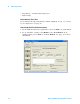
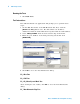
Configuring the Tests
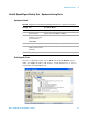
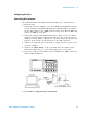
Connecting the Equipment - Differential Connection
The USB automated test application will prompt you to perform these
connection steps:
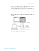
1 Attach the 5V power supply to J5 of the E2649- 66401 (E2645- 66507 if
you are using the old fixture) Device Hi- Speed Signal Quality test
fixture. Leave the TEST switch at the OFF position. Verify green Power
LED is lit, and yellow test LED is off.
2 Connect the [TEST PORT] of the test fixture into the upstream facing
port of the hub under test, using the 4" USB cable.
3 Connect the [INIT PORT] of the test fixture to a hi- speed port of the
Test Bed Computer. Apply power to the hub.
4 Attach the Agilent 113xA differential probe to D+/D- of TP2 on the test
fixture, using the header adapter (the header adapter is only needed if
you are using the old test fixture). Ensure the + polarity on the probe
lines up with D+ on the fixture.
5 If you are using the new fixture, please terminate the SMA connectors
with 50 Ohm terminators.
6 Check I have completed these instructions.
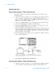
Connecting the Equipment - Single-Ended Connection.
1 Attach the 5V power supply to J5 of the E2649- 66401 (E2645- 66507 if
you are using the old fixture) Device Hi- Speed signal quality test