
Technical data

230 Notes on USB Electrical Compliance Testing
8 On-The-Go Electrical Tests
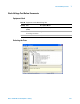
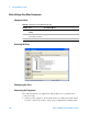
Configuring the Tests
If the power supply’s SICL address is different from the default, make sure
you set the E3631A Instrument Address configuration option to the power
supply’s SICL address.
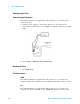
Connecting the Equipment
The USB automated test application will prompt you to perform these
connection steps:
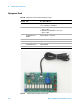
1 Please refer to the “Installing the USB- OET (OTG Electrical Test)
Fixture Driver" on page 229 for instructions on installing the drivers for
the N5417A OTG Electrical Test board.
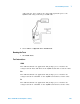
2 Connect the Channel 1 probe of the oscilloscope to the J100, VBUS test
point of the OET. Connect the probe's ground to the J104, GND test
point nearest to the VBUS test point.
3 Connect the Channel 3 probe of the oscilloscope to the J102, D+ test
point of the OET. Connect the probe's ground to the J105, GND test
point nearest to the D+ test point.
4 Connect the black multimeter lead from INPUT LOW to J110, GND
terminal, of the OET.
5 Connect the red multimeter lead from INPUT HI to J108, VBUS
terminal, of the OET.
6 Connect the black supply lead from the power supply 6 volt supply
negative output to J109, GND terminal, of the OET.
7 Connect the red power supply lead from the power supply 6 volt supply
positive output to J107, Switched VBUS terminal, of the OET.
8 Connect the 34401A digital multi- meter to E3631A power supply using
the 10833B GPIB cable.
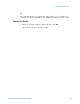
NOTE
Note: For 54831B/D and 54832B/D oscilloscopes, use 1165A passive probes. For the
5485XA, 80000 and 90000A Series oscilloscpes, use 1156A active probes.
WARNING
Make sure the power supply voltage is 6 V. An incorrect voltage can damage the
USB-OET test fixture, and a damaged test fixture can be a shock hazard to the
operator.