
Technical data

212 Notes on USB Electrical Compliance Testing
7 Low and Full Speed Tests
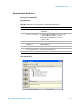
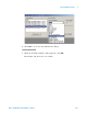
Configuring the Tests Make sure you set the Test Type configuration option
to “Low- Speed Far End” before running the test.
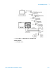
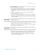
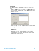
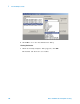
Connecting the Equipment The USB automated test application will prompt
you to perform these connection steps:
1 For 54831B/D and 54832B/D oscilloscopes, use 1165A passive probes.
For the 5485XA, 80000 and 90000A Series oscilloscpes, use E2697A
high- impedance converter with 10:1 passive probes, or 1156A active
probes.
2 Attach the passive probes to the oscilloscope's Channel 2, Channel 3
and Channel 1 inputs.
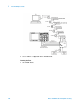
3 Attach the SQiDD board to two USB ports at the end of 5 self- powered
hubs and a host system. Hub #1 has to be a hi- speed hub and hub #2
has to be a full speed hub. The rest of the hubs can be either hi- speed
or full speed hubs.
4 Attach a low speed device under test to the same section of the SQiDD
board. If the section has a switch, it should be set to ON.
5 Attach another low speed device to the adjacent section of the SQiDD
board. This is for triggering purposes.
6 Connect the oscilloscope Channel 2 probe to D- probe point of the
device under test portion. Connect the oscilloscope Channel 3 probe to
the D+ probe point of the device under test portion. Connect the
oscilloscope Channel 1 probe to the D- probe point on the adjacent
device section of the SQiDD board.
NOTE
Placing a full speed and/or a high-speed device downstream of a full speed hub forces both
to operate in full speed mode.