
Technical data

156 Notes on USB Electrical Compliance Testing
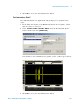
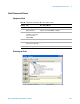
5 Host Hi-Speed Electrical Tests
Configuring the Tests
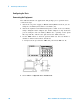
Connecting the Equipment
The USB automated test application will prompt you to perform these
connection steps:
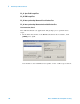
1 Attach the 5V power supply to E2649- 66404 (E2645- 66506 if you are
using the old fixture) Disconnect test fixture (J5).
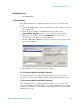
2 Attach the Agilent 113xA differential probe to TP2 of the test fixture,
using a damped header adapter (the header adapter is only needed if
you are using the old test fixture). Ensure the + polarity on the probe
lines up with D+, which is the pin nearest the USB connector.
3 Set the TEST switch to the Test position. This sets the test fixture to
emulate a must- not- disconnect threshold.
a Verify both the green Power LED and yellow Test LED are lit.
4 Check I have completed these instructions.