
Technical data

144 Notes on USB Electrical Compliance Testing
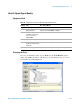
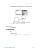
5 Host Hi-Speed Electrical Tests
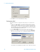
Configuring the Tests
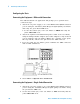
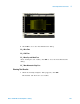
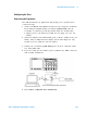
Connecting the Equipment - Differential Connection
The USB automated test application will prompt you to perform these
connection steps:
1 Attach the 5V power supply to J5 of the E2649- 66402 (E2645- 66508 if
you are using the old fixture) Host Hi- Speed Signal Quality test fixture
and verify the green Power LED is lit.
a Set the Test switch (S1) of the test fixture to TEST and verify the
yellow TEST LED is lit.
2 Attach the Agilent 113xA differential probe to TP2 of the test fixture,
using the damped header adapter (the header adapter is only needed if
you are using the old test fixture). Ensure the + polarity on the probe
lines up with D+, which is the pin nearest the USB connector.
3 If you are using the new fixture, please terminate the SMA connectors
with 50 Ohm terminators.
4 Check I have completed these instructions.
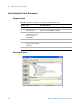
Connecting the Equipment - Single-Ended Connection
1 Attach the 5V power supply to J5 of the E2649- 66402 (E2645- 66508 if
you are using the old fixture) Hi- Speed signal quality test fixture. Verify
the green Power LED is lit.
2 Set the Test switch (S1) of the test fixture to TEST and verify that the
yellow TEST LED is lit.