Agilent N5416A USB 2.
Notices © Agilent Technologies, Inc. 1997 – 2013 Manual Part Number No part of this manual may be reproduced in any form or by any means (including electronic storage and retrieval or translation into a foreign language) without prior agreement and written consent from Agilent Technologies, Inc. as governed by United States and international copyright laws. N5416-97007 Edition Tenth edition, April 2013 Available in electronic format only Agilent Technologies, Inc.
USB Automated Testing—At A Glance The Agilent N5416A USB 2.0 compliance test option helps you verify USB compliance to specifications using the Agilent 5485xA, 9000 or 80000 or 90000A Series Infiniium digital storage oscilloscope. The USB 2.0 compliance test option runs under an automated test engine that. • Lets you select individual or multiple tests to run. • Lets you identify the device being tested and its configuration. • Shows you how to make oscilloscope connections to the device under test.
In This Book This manual contains notes on the electrical tests that are performed by the USB 2.0 compliance test option; it describes the equipment used, and it describes how the tests are performed. • Chapter 1, “Installing the USB 2.0 Compliance Test Option” shows how to install and license the automated test application software (if it was purchased separately). • Chapter 2, “Preparing to Take Measurements” describes the equipment required, how to set up the equipment, how to start the USB 2.
Contents USB Automated Testing—At A Glance In This Book 3 4 1 Installing the USB 2.0 Compliance Test Option Installing the Software Installing the License Key 16 17 2 Preparing to Take Measurements Required Equipment and Software 20 Oscilloscope, Software, and Accessories 20 High-Speed Electrical Test Bed Computer 22 E2649B USB 2.
Device Packet Parameters 41 Equipment Used 41 Selecting the Tests 41 Configuring the Tests 42 Connecting the Equipment 42 Running the Tests 43 Test Instructions, Part 1 43 Test Instructions, Part 2 44 Viewing Test Results 47 Device CHIRP Timing 48 Equipment Used 48 Selecting the Tests 48 Configuring the Tests 49 Connecting the Equipment Running the Tests 50 Test Instructions 50 Viewing Test Results 50 49 Device Suspend/Resume/Reset Timing Equipment Used 51 Selecting the Tests 51 Configuring the Tests 52 C
Device Receiver Sensitivity 65 Equipment Used 65 Selecting the Tests 66 Configuring the Tests 66 Connecting the Equipment 67 Running the Tests 68 Test Instructions 68 Viewing Test Results 70 4 Hub Hi-Speed Tests Hub Hi-Speed Signal Quality Test - Upstream Facing Ports 73 Equipment Used 73 Selecting the Tests 73 Configuring the Tests 74 Connecting the Equipment - Differential Connection 74 Connecting the Equipment - Single-Ended Connection.
Hub Disconnect Detect 86 Equipment Used 86 Selecting the Tests 86 Configuring the Tests 87 Connecting the Equipment Running the Tests 88 Test Instructions 88 Viewing Test Results 89 87 Hub Packet Parameters - Upstream Facing Port Equipment Used 90 Selecting the Tests 90 Configuring the Tests 91 Connecting the Equipment 91 Running the Tests 92 Test Instructions, Part 1 92 Test Instructions, Part 2 93 Viewing Test Results 96 90 Hub Receiver Sensitivity - Upstream Facing Port Equipment Used 97 Selecting th
Hub Repeater Test - Upstream Facing Port Equipment Used 111 Selecting the Tests 112 Configuring the Tests 112 Connecting the Equipment 112 Running the Tests 114 Test Instructions, Part 1 114 Test Instructions, Part 2 115 Viewing Test Results 116 111 Hub CHIRP Timing - Upstream Facing Port Equipment Used 117 Selecting the Tests 117 Configuring the Tests 118 Connecting the Equipment 118 Running the Tests 119 Test Instructions 119 Viewing Test Results 119 117 Hub Suspend/Resume/Reset Timing - Upstream Faci
Hub Test J/K, SE0_NAK - Downstream Facing Port Equipment Used 134 Selecting the Tests 134 Configuring the Tests 135 Connecting the Equipment 135 Running the Tests 136 Test Instructions 136 Viewing Test Results 139 134 5 Host Hi-Speed Electrical Tests Host Hi-Speed Signal Quality 143 Equipment Used 143 Selecting the Tests 143 Configuring the Tests 144 Connecting the Equipment - Differential Connection 144 Connecting the Equipment - Single-Ended Connection 144 Running the Tests 145 Test Instructions, Part 1
Host CHIRP Timing 159 Equipment Used 159 Selecting the Tests 159 Configuring the Tests 160 Connecting the Equipment 160 Running the Tests 162 Test Instructions 162 Viewing Test Results 163 Host Suspend/Resume Timing 164 Equipment Used 164 Selecting the Tests 164 Configuring the Tests 165 Connecting the Equipment 165 Running the Tests 166 Test Instructions 166 Viewing Test Results 168 Host Test J/K, SE0_NAK 169 Equipment Used 169 Selecting the Tests 169 Configuring the Tests 170 Connecting the Equipment 170
Inrush Current Test 197 Equipment Used 197 Selecting the Tests 197 Configuring the Tests 198 Connecting the Equipment 198 Running the Tests 199 Test Instructions, Part 1 199 Test Instructions, Part 2 199 Viewing Test Results 199 Signal Integrity Test 200 Host Downstream Signal Quality Test Hub Downstream Signal Quality Test Upstream Signal Quality Test 211 Back-Voltage Test Before Enumerate Equipment Used 221 Selecting the Tests 221 Configuring the Tests 222 Connecting the Equipment 222 Running the Tests 22
Running the Tests 231 E1 E8 A-Device Output Voltage 231 E3 VBUS Rise Time 232 E5 B-Device (SRP capable) to OTG Device Output Voltage E6 B-Device (SRP capable) to Host Output Voltage 232 E19 A-Device Session Valid 232 E20 B-Device VBUS Valid 233 E22 Data-Line Pulsing Test 233 A-Device VBUS Valid (VA_VBUS_VLD) 233 Viewing Test Results 232 233 Index Notes on USB Electrical Compliance Testing 13
Notes on USB Electrical Compliance Testing
N5416A USB 2.0 Compliance Test Option Notes on Electrical Testing 1 Installing the USB 2.0 Compliance Test Option Installing the Software 16 Installing the License Key 17 If you purchased the N5416A USB 2.0 Compliance Test Option separately, you need to install the software and license key.
1 Installing the USB 2.0 Compliance Test Option Installing the Software 1 Make sure you have the correct Infiniium software version by choosing Help>About Infiniium... from the main menu. • Version 5.71 or greater of Infiniium software 80000 Series Infiniium Digital Storage Oscilloscope OR • Version 1.41 or greater of Infiniium software 90000A Series Infiniium Digital Storage Oscilloscope OR • Version 2.00 or greater of Infiniium software 9000A Series Infiniium Digital Storage Oscilloscope.
Installing the USB 2.0 Compliance Test Option 1 Installing the License Key 1 Request a license code from Agilent by following the instructions on the Entitlement Certificate. You will need the oscilloscope’s “Option ID Number”, which you can find in the Help>About Infiniium... dialog. 2 After you receive your license code from Agilent, choose Utilities>Install Option License.... 3 In the Install Option License dialog, enter your license code and click Install License.
1 18 Installing the USB 2.
N5416A USB 2.0 Compliance Test Option Notes on Electrical Testing 2 Preparing to Take Measurements Required Equipment and Software 20 Setting Up the Equipment 25 Starting the USB 2.0 Compliance Test Option 28 Running Tests 31 This chapter lists all of the required equipment for running the compliance tests. It also includes information on the fundamental equipment connections, accessing help, and running the software.
2 Preparing to Take Measurements Required Equipment and Software The following tables list the required test equipment and the tests for which they are required. Oscilloscope, Software, and Accessories Table 1 Digital Storage Oscilloscope, Software, and Accessories TESTS Equipment Required Host Hub Device Low/Full Hi-Speed Hi-Speed Hi-Speed Speed Agilent 5485xA, 9000A or 80000 or 90000A Series Infiniium oscilloscope. 1*,† 1a,b 1a,b 1a,b Agilent N5416A USB Compliance Test Option.
Preparing to Take Measurements Table 2 2 Digital Multimeter TESTS Equipment Required Host Hub Device Low/Full Hi-Speed Hi-Speed Hi-Speed Speed Agilent 33401A digital multimeter or equivalent. 1 1 1 1 Mini-clip DMM leads - one each of black and red color. 1 1 1 1 Table 3 Digital Signal Generator TESTS Equipment Required Host Hub Device Low/Full Hi-Speed Hi-Speed Hi-Speed Speed Agilent 81130A Pulse/Pattern Generator with 2 channels of Agilent 81132A (660 MHz) option.
2 Preparing to Take Measurements Table 4 Miscellaneous Cables and Devices (continued) TESTS Host Hub Device Low/Full Hi-Speed Hi-Speed Hi-Speed Speed Equipment Required USB self-powered hub (and power supply). These are the hubs used for compliance testing and are available from the USB-IF. For development testing, in most cases, a hub that has passed USB compliance testing can be used. n/a n/a n/a 5 High-Speed Electrical Test Bed Computer The high- speed electrical test bed computer hosts a USB 2.
2 Preparing to Take Measurements E2649B USB 2.0 High-Speed Fixture Set The E2649B high- speed fixture set includes five test fixtures. In the test procedures, separate instructions may be provided based on the version of the fixture that is being used. Fixture versions are identified by a part number, which are shown in the following table and marked on the fixture. N O TE Table 6 The fixture part numbers are provided for identification purposes only and cannot be used for ordering.
2 Preparing to Take Measurements Table 8 Contents of E2649B USB 2.0 High-Speed Fixture Set Equipment Required Qty P/N USB to right-angle DC-plug cable, 2m long, 1 8121-1966 USB 2.0 A (m) to USB 2.0 micro-B (m) cable, 4 inch 1 8121-2153 Device Hi-Speed Signal Quality test fixture.
2 Preparing to Take Measurements Setting Up the Equipment Infiniium 5485xA, 9000A, 80000 and 90000A Series Digital Sampling Oscilloscope 1 Connect keyboard and mouse to oscilloscope. 2 Connect optional computer monitor to the VGA connector on the rear nearest the right side of the instrument. Differential Connection 3 Attach the Agilent 113xA differential probe to Channel 1 of the oscilloscope. a Attach the socketed probe head to the differential probe amp.
2 Preparing to Take Measurements 4 Attach the E2697A adapters or 1156A probes to Channels 2 and 3. a When using the E2697A adapter, connect the 10073C miniature passive probes to the E2697A adapter. N O TE These probe assignments will be used through out the entire test procedure. 5 Turn on the oscilloscope to allow 30 minutes of warm up time prior to use. 6 Configure the second monitor, if being used, while the oscilloscope is warming up.
Preparing to Take Measurements 2 81130A Digital Signal Generator The digital signal generator is needed to perform hi- speed hub and device receiver sensitivity tests. For energy conservation, you may choose to turn on the digital signal generator about 15 minutes prior to performing these measurements.
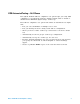
2 Preparing to Take Measurements Starting the USB 2.0 Compliance Test Option 1 From the Infiniium oscilloscope’s main menu, choose Analyze>Automated Test Apps>USB Test. Figure 2 N O TE The USB 2.0 Compliance Test Option If “USB Test” does not appear in the Automated Test Apps menu, the USB 2.0 Compliance Test Option has not been installed (see Chapter 1, “Installing the USB 2.0 Compliance Test Option”). Figure 2 shows the USB 2.0 Compliance Test Option main window.
Preparing to Take Measurements Set Up Lets you identify the test environment, including information about the device being tested and other test instruments that can be automatically configured. The new Hi- Speed fixtures allow you to choose between either differential or single- ended connections (old fixtures only permit differential connections). The Test Method choice lets you choose between doing tests automatically or manually. If you want to do the tests automatically, select Matlab for this box.
2 Preparing to Take Measurements Online Help Topics For information on using the USB 2.0 Compliance Test Option, see its online help (which you can access by choosing Help>Contents... from the application’s main menu). The USB 2.0 Compliance Test Option’s online help describes: • Creating or opening a test project. • Selecting tests. • Configuring selected tests. • Connecting the oscilloscope to the DUT. • Running tests. • Viewing test results. • To show reference images and flash mask hits.
Preparing to Take Measurements 2 Running Tests To run USB electrical compliance tests: 1 Select the tests you want to run. 2 Change test configuration options if necessary. 3 Connect the oscilloscope to the device under test. 4 Run the tests. 5 View the detailed test results. 6 View/print the HTML test report.
2 32 Preparing to Take Measurements Notes on USB Electrical Compliance Testing
N5416A USB 2.
3 Device Hi-Speed Tests Selecting the Device Test Environment Setup 1 In the USB automated test application, select the Device test environment. 2 To do automatic testing, select Matlab as the Test Method. To do manual testing, select Both as the Test Method. See page 23 for more information.
Device Hi-Speed Tests 3 Device Hi-Speed Signal Quality Test Equipment Used Table 9 Equipment Used in Device Hi-Speed Signal Quality Tests Quantity Item Description/Model 1 Oscilloscope Agilent 5485xA, 9000A Series, 80000 or 90000A Series 1 Differential probe Agilent 113xA with E2699A or E2678A 1 Header adapter (only needed if you are using the old test fixture E2645-66507) Agilent 01131-68703 1 Host test bed computer Any computer with hi-speed USB ports 1 Device Hi-Speed Signal Agilent E2
3 Device Hi-Speed Tests Configuring the Tests Connecting the Equipment - Differential Connection The USB automated test application will prompt you to perform these connection steps: 1 Attach the 5V power supply to J5 of the E2649- 66401 (E2645- 66507 if you are using the old fixture) Device Hi- Speed signal quality test fixture. Leave the TEST switch at the OFF position. Verify the green Power LED is lit and the yellow Test LED is not lit.
Device Hi-Speed Tests 3 Connecting the Equipment - Single-Ended Connection 1 Attach the 5V power supply to J5 of the E2649- 66401 (E2645- 66507 if you are using the old fixture) Device Hi- Speed signal quality test fixture. Leave the TEST switch at the OFF position. Verify the green Power LED is lit and the yellow Test LED is not lit. 2 Connect the [TEST PORT] of the Device Hi- speed Signal Quality test fixture into the upstream facing port of the device under test, using the 4" USB cable.
3 Device Hi-Speed Tests Running the Tests 1 Click Run Tests. Test Instructions, Part 1 The USB automated test application will prompt you to perform these steps: 1 Invoke the HS Electrical Test Tool software on the Hi- Speed Electrical Test Bed computer. 2 Select Device and click the [TEST] button to enter the Device Test menu. 3 Click OK to close the Test Instructions dialog.
Device Hi-Speed Tests 3 3 Place the Test Switch (S1) in the TEST position. Verify the yellow TEST LED is lit. You should see the transmitted test packet on the oscilloscope as below. 4 Click OK to close the Test Instructions dialog. EL_6 Rise Time EL_6 Fall Time EL_2 EL_4 EL_5 Data Eye and Mask Test After viewing the test results, click OK to close the Test Instructions dialog.
3 Device Hi-Speed Tests EL_7 Non-Monotonic Edge Test Viewing Test Results 1 When the Testing Complete dialog appears, click OK. The Results tab shows the test results.
Device Hi-Speed Tests 3 Device Packet Parameters Equipment Used Table 10 Equipment Used in Device Packet Parameters Tests Quantity Item Description/Model 1 Oscilloscope Agilent 5485xA, 9000A Series, 80000 or 90000A Series 1 Differential probe Agilent 113xA with E2699A or E2678A 1 Header adapter (only needed if you are using the old test fixture E2645-66507) Agilent 01131-68703 1 Host test bed computer Any computer with hi-speed USB ports 1 Device Hi-Speed Signal Agilent E2649-66401 (old fix
3 Device Hi-Speed Tests Configuring the Tests Connecting the Equipment The USB automated test application will prompt you to perform these connection steps: 1 Remove the 5V supply. Connect the E2649- 66401 (E2645- 66507 if you are using the old fixture) Device Hi- Speed Signal Quality test fixture ([INIT PORT]) into a high- speed capable port of the test bed, using a USB cable.
Device Hi-Speed Tests 3 Running the Tests 1 Click Run Tests. Test Instructions, Part 1 The USB automated test application will prompt you to perform these steps: 1 Cycle the device power to restore the device to normal operation. On the Device Test Menu of the HS Electrical Tool, click Enumerate Bus once. 2 Using the oscilloscope, verify the SOFs (Start Of Frame) packets are being transmitted on the port under test. You may need to lower the trigger level to somewhat below 400 mV.
3 Device Hi-Speed Tests 3 Click OK to close the Test Instructions dialog. Test Instructions, Part 2 The USB automated test application will prompt you to perform these steps: 1 In the Device Test menu of the HS Electrical Test Tool, ensure that the hub under test is selected. 2 Select SINGLE STEP SET FEATURE from the Device Command window. Click [EXECUTE] once.
Device Hi-Speed Tests 3 3 You should see the transmitted test packet on the oscilloscope as below. 4 Click OK to close the Test Instructions dialog.
3 Device Hi-Speed Tests EL_21 Sync Field Length Test EL_25 EOP Length Test EL_22 Measure Interpacket Gap Between Second and Third Packets EL_22 Measure Interpacket Gap Between First and Second Packets The USB automated test application will prompt you to perform these steps: 1 In the Device Test menu of the HS Electrical Test Tool, click [STEP] once again. This is the second step of the two- step Single Step Set Feature command. 2 You should see the transmitted test packet on the oscilloscope as below.
Device Hi-Speed Tests 3 3 Click OK to close the Test Instructions dialog. Viewing Test Results 1 When the Testing Complete dialog appears, click OK. The Results tab shows the test results.
3 Device Hi-Speed Tests Device CHIRP Timing Equipment Used Table 11 Equipment Used in Device CHIRP Timing Tests Quantity Item Description/Model 1 Oscilloscope Agilent 5485xA, 9000A Series, 80000 or 90000A Series 2 Passive or active probes Agilent E2697A with 10073C, or 1156A 1 Host test bed computer Any computer with hi-speed USB ports 1 Device Hi-Speed Signal Agilent E2649-66401 (old fixture P/N E2645-66507) Quality test fixture and 4” USB cable 1 5 meter USB 2.
3 Device Hi-Speed Tests Configuring the Tests Connecting the Equipment The USB automated test application will prompt you to perform these connection steps: 1 Connect the E2697A with 10073C passive probe or the 1156A active probe on Channel 2 to the D- pin at TP2 of the E2649- 66401 (E2645- 66507 if you are using the old fixture) Device Hi- Speed Signal Quality test fixture. 2 Connect the E2697A with 10073C passive probe or the 1156A active probe on Channel 3 to the D+ pin at TP2.
3 Device Hi-Speed Tests Running the Tests 1 Click Run Tests. Test Instructions The USB automated test application will prompt you to perform these steps: 1 On the HS Electrical Test Tool software, click [Enumerate Bus] once. You should capture the CHIRP handshake as in the below figure. 2 Click OK to close the Test Instructions dialog.
Device Hi-Speed Tests 3 Device Suspend/Resume/Reset Timing Equipment Used Table 12 Equipment Used in Device Suspend/Resume/Reset Timing Tests Quantity Item Description/Model 1 Oscilloscope Agilent 5485xA, 9000A Series, 80000 or 90000A Series 2 Passive or active probes Agilent E2697A with 10073C, or 1156A 1 Host test bed computer Any computer with hi-speed USB ports 1 Device Hi-Speed Signal Agilent E2649-66401 (old fixture P/N E2645-66507) Quality test fixture and 4” USB cable 1 5 meter USB 2
3 Device Hi-Speed Tests Configuring the Tests Connecting the Equipment The USB automated test application will prompt you to perform these connection steps: 1 Connect the E2697A with 10073C passive probe or the 1156A active probe on Channel 2 to the D- pin at TP2 of the E2649- 66401 (E2645- 66507 if you are using the old fixture) Device Hi- Speed Signal Quality test fixture. 2 Connect the E2697A with 10073C passive probe or the 1156A active probe on Channel 3 to the D+ pin at TP2.
Device Hi-Speed Tests 3 Running the Tests 1 Click Run Tests. Test Instructions EL_38 EL_39 Suspend Timing Response The USB automated test application will prompt you to perform these steps: 1 On the Device Test Menu of the HS Electrical Test Tool software, click [Enumerate Bus] once. 2 Select SUSPEND from the Device Command drop down menu. Click [EXECUTE] once to place the device into suspend. The captured transition should be as in the figure below.
3 Device Hi-Speed Tests 3 Click OK to close the Test Instructions dialog. EL_40 Resume Timing Response The USB automated test application will prompt you to perform these steps: 1 On the Device Test Menu of the HS Electrical Test Tool, select RESUME from the Device Command drop down menu. Click [EXECUTE] once to resume the hub from suspend. The captured transition should be as in the figure below.
3 Device Hi-Speed Tests 2 Click OK to close the Test Instructions dialog. EL_27 Device CHIRP Response to Reset from Hi-Speed Operation The USB automated test application will prompt you to perform these steps: 1 On the Device Test Menu of the HS Electrical Test Tool, select RESET from the Device Command drop down menu. Click [EXECUTE] once to reset the device operating in high speed. The captured transition should be as in the figure below.
3 Device Hi-Speed Tests 2 Click OK to close the Test Instructions dialog. EL_28 Device CHIRP Response to Reset from Suspend The USB automated test application will prompt you to perform these steps: 1 On the Device Test Menu of the HS Electrical Test Tool software, select SUSPEND from the Device Command drop down menu. Click [EXECUTE] once to place the device into suspend. 2 Click OK to close the Test Instructions dialog.
3 Device Hi-Speed Tests The USB automated test application will prompt you to perform these steps: 1 On the Device Test Menu of the HS Electrical Test Tool, select RESET from the Device Command drop down menu. Click [EXECUTE] once to reset the device operating in high speed. The captured transition should be as in the figure below. 2 Click OK to close the Test Instructions dialog.
3 Device Hi-Speed Tests Viewing Test Results 1 When the Testing Complete dialog appears, click OK. The Results tab shows the test results.
Device Hi-Speed Tests 3 Device Test J/K, SE0_NAK Equipment Used Table 13 Equipment Used in Device Test J/K, SE0_NAK Tests Quantity Item Description/Model 1 Digital Multimeter (DMM) Agilent 34401A or equivalent 1 Host test bed computer Any computer with hi-speed USB ports 1 Device Hi-Speed Signal Agilent E2649-66401 (old fixture P/N E2645-66507) Quality test fixture and 4” USB cable 1 5V power supply Agilent 0950-2546 or equivalent 1 5 meter USB 2.
3 Device Hi-Speed Tests Configuring the Tests Connecting the Equipment The USB automated test application will prompt you to perform these connection steps: 1 Attach the 5V power supply to J5 of the E2649- 66401 (E2645- 66507 if you are using the old fixture) Device High- Speed Signal Quality test fixture. 2 Place the switch in the test switch to OFF position. Verify the green Power LED is lit, and the yellow Test LED is off.
Device Hi-Speed Tests 3 Running the Tests 1 Click Run Tests. Test Instructions EL_8 J Test The USB automated test application will prompt you to perform these steps: 1 On the Device Test Menu of the HS Electrical Test Tool, click [Enumerate Bus] once. 2 Select TEST_J from the Device Command drop down menu. Click [EXECUTE] once to place the device into TEST_J test mode. 3 Switch the test fixture into the TEST position. 4 Click OK to close the Test Instructions dialog.
3 Device Hi-Speed Tests EL_8 K Test The USB automated test application will prompt you to perform these steps: 1 Return the Test switch of the test fixture to the NORMAL position. 2 Cycle the device power to restore the device to normal operation. On the Device Test Menu of the HS Electrical Test Tool, click [Enumerate Bus] once. 3 Select TEST_K from the Device Command drop down menu. Click [EXECUTE] once to place the device into TEST_K test mode. 4 Switch the test fixture into the TEST position.
3 Device Hi-Speed Tests The USB automated test application will prompt you for the following voltage measurements: EL_9 SE0_NAK Test The USB automated test application will prompt you to perform these steps: 1 Return the Test switch of the test fixture to the NORMAL position. 2 Cycle the device power to restore the device to normal operation. On the Device Test Menu of the HS Electrical Test Tool, click [Enumerate Bus] once. 3 Select TEST_SE0_NAK from the Device Command drop down menu.
3 Device Hi-Speed Tests 5 Click OK to close the Test Instructions dialog. The USB automated test application will prompt you for the following voltage measurements: Viewing Test Results 1 When the Testing Complete dialog appears, click OK. The Results tab shows the test results.
Device Hi-Speed Tests 3 Device Receiver Sensitivity Equipment Used Table 14 Equipment Used in Device Receiver Sensitivity Tests Quantity Item Description/Model 1 Oscilloscope Agilent 5485xA, 9000A Series, 80000 or 90000A Series 1 Differential probe Agilent 113xA with E2699A or E2678A 1 Header adapter (only needed if you are using the old test fixture E2645-66503) Agilent 01131-68703 1 Host test bed computer Any computer with hi-speed USB ports 1 Receiver Sensitivity test fixture and 4” USB
3 Device Hi-Speed Tests Selecting the Tests Configuring the Tests If the pulse generator’s SICL address is different from the default, make sure you set the 81134A/81130A Instrument Address configuration option to the pulse generator’s SICL address. See also “Configuring the 81134A pulse generator using the 82357A GPIB- USB converter" on page 98.
3 Device Hi-Speed Tests Connecting the Equipment The USB automated test application will prompt you to perform these connection steps: 1 Attach the 5V power supply to the E2649- 66403 (E2645- 66503 if you are using the old fixture) Device Receiver test fixture (J5). a Verify the green Power LED is lit. b Leave the TEST switch at the OFF position (S1). c The yellow LED should be off. 2 Connect the [INIT PORT] of the fixture to a Hi- Speed port on the Test Bed Computer, using the 5 meter USB cable.
3 Device Hi-Speed Tests 5 Connect the 81130A or 81134A pulse generator to the oscilloscope using the 82357A USB/GPIB Interface. a If you choose to use the Agilent 81130A Pulse/Pattern Generator, connect the 8493C 6dB attenuators to OUTPUT1 and OUTPUT2 of Agilent 81130A Pulse/Pattern Generator. b If you choose to use the Agilent 81134A Pulse/Pattern Generator, connect the 15433B Transition Time Converters to OUTPUT1 and OUTPUT2 of Agilent 81134A Pulse/Pattern Generator.
Device Hi-Speed Tests 3 3 Place the test fixture Test Switch (S1) into the TEST position. This switches in the data generator in place of the host controller. The data generator emulates the "IN" packets from the host controller. 4 Click OK to close the Test Instructions dialog.
3 Device Hi-Speed Tests EL_18 Receiver sensitivity Test - Minimum SYNC Field EL_17 Receiver sensitivity Test EL_16 Receiver sensitivity Test @ Squelch Viewing Test Results 1 When the Testing Complete dialog appears, click OK. The Results tab shows the test results.
N5416A USB 2.
4 Hub Hi-Speed Tests • Drop/Droop – Downstream facing ports. • Back- voltage. Before Running These Tests If you haven’t already performed the initial equipment set up, see “Setting Up the Equipment" on page 25. Selecting the Hub Test Environment Setup 1 In the USB automated test application, select the Hub test environment. 2 To do automatic testing, select Matlab as the Test Method. To do manual testing, select Both as the Test Method. See page 23 for more information.
Hub Hi-Speed Tests 4 Hub Hi-Speed Signal Quality Test - Upstream Facing Ports Equipment Used Table 15 Equipment Used in Hub Hi-Speed Signal Quality Test - Upstream Facing Ports Quantity Item Description/Model 1 Oscilloscope Agilent 5485xA, 9000A Series, 80000 or 90000A Series 1 Differential probe Agilent 113xA with E2699A or E2678A 1 Header adapter (only needed if you are using the old test fixture E2645-66507) Agilent 01131-68703 1 Host test bed computer Any computer with hi-speed USB ports
4 Hub Hi-Speed Tests Configuring the Tests Connecting the Equipment - Differential Connection The USB automated test application will prompt you to perform these connection steps: 1 Attach the 5V power supply to J5 of the E2649- 66401 (E2645- 66507 if you are using the old fixture) Device Hi- Speed Signal Quality test fixture. Leave the TEST switch at the OFF position. Verify green Power LED is lit, and yellow test LED is off.
Hub Hi-Speed Tests 4 fixture. Leave the TEST switch at the OFF position. Verify the green Power LED is lit and the yellow Test LED is not lit. 2 Connect the [TEST PORT] of the Device Hi- speed Signal Quality test fixture into the upstream facing port of the device under test, using the 4" USB cable. 3 Connect the [INIT PORT] of the test fixture to a Hi- speed capable port of the Test Bed Computer, using the 5 meter USB cable. 4 Apply power to the device.
4 Hub Hi-Speed Tests Running the Tests 1 Click Run Tests. Test Instructions, Part 1 The USB automated test application will prompt you to perform these steps: 1 Invoke the HS Electrical Test Tool software on the Hi- Speed Electrical Test Bed computer. Select Hub and click the [TEST] button to enter the Hub Test menu. 2 The hub under test should be enumerated with the hub's VID shown together with the USB address. Select [TEST_PACKET] from the Hub Command drop down menu and click [EXECUTE].
4 Hub Hi-Speed Tests 3 Click OK to close the Test Instructions dialog. Test Instructions, Part 2 The USB automated test application will prompt you to perform these steps: 1 Place the Test Switch (S1) of the test fixture in the TEST position. Verify the yellow TEST LED is lit. You should see the transmitted test packet on the oscilloscope as below. 2 Click OK to close the Test Instructions dialog.
4 Hub Hi-Speed Tests Hub Hi-Speed Signal Quality Test - Downstream Facing Ports Equipment Used Table 16 Equipment Used in Hub Hi-Speed Signal Quality Test - Downstream Facing Ports Quantity Item Description/Model 1 Oscilloscope Agilent 5485xA, 9000A Series, 80000 or 90000A Series 1 Differential probe Agilent 113xA with E2699A or E2678A 1 Header adapter (only needed if you are using the old test fixture E2645-66508) Agilent 01131-68703 1 Host test bed computer Any computer with hi-speed USB po
Hub Hi-Speed Tests 4 Configuring the Tests Connecting the Equipment The USB automated test application will prompt you to perform these connection steps: 1 Attach the 5V power supply to J5 of the E2649- 66402 (E2545- 66508 if you are using the old fixture) Host Hi- Speed Signal Quality test fixture. Set the Test switch to the TEST position. Verify green Power LED and yellow test LED are both lit.
4 Hub Hi-Speed Tests Running the Tests 1 Click Run Tests. Test Instructions The USB automated test application will prompt you to perform these steps: 1 On the Hub Test menu of the HS Electrical Test Tool, click the [Enumerate Bus] button once. The hub under test should be enumerated with the hub's VID shown together with the USB address. 2 Select TEST_PACKET from the Port Control drop down menu. 3 Enter the port number of the hub port being tested and click [EXECUTE].
Hub Hi-Speed Tests 4 Viewing Test Results 1 When the Testing Complete dialog appears, click OK. The Results tab shows the test results.
4 Hub Hi-Speed Tests Hub Jitter Test - Downstream Facing Ports Equipment Used Table 17 Equipment Used in Hub Jitter Test - Downstream Facing Ports Quantity Item Description/Model 1 Oscilloscope Agilent 5485xA, 9000A Series, 80000 or 90000A Series 1 Differential probe Agilent 113xA with E2699A or E2678A 1 Header adapter (only needed if you are using the old test fixture E2645-66508) Agilent 01131-68703 1 Host test bed computer Any computer with hi-speed USB ports 1 Host Hi-Speed Signal Agile
Hub Hi-Speed Tests 4 Configuring the Tests Connecting the Equipment The USB automated test application will prompt you to perform these connection steps: 1 Attach the 5V power supply to J5 of the E2649- 66402 (E2645- 66508 if you are using the old fixture) Host Hi- Speed Signal Quality test fixture. Set the Test switch to the TEST position. Verify green Power LED and yellow test LED are both lit.
4 Hub Hi-Speed Tests Running the Tests 1 Click Run Tests. Test Instructions EL_47 Data Eye and Mask Test The USB automated test application will prompt you to perform these steps: 1 On the Hub Test menu of the HS Electrical Test Tool, click [Enumerate Bus] once. 2 Select TEST_FORCE_ENABLE from the Port Control drop down menu. 3 Enter the port number of the hub port being tested and click [EXECUTE] once to force- enable the hub port under test.
Hub Hi-Speed Tests 4 5 Click OK to close the Test Instructions dialog. After viewing the test results, click OK to close the Test Instructions dialog. Viewing Test Results 1 When the Testing Complete dialog appears, click OK. The Results tab shows the test results.
4 Hub Hi-Speed Tests Hub Disconnect Detect Equipment Used Table 18 Equipment Used in Hub Disconnect Detect Quantity Item Description/Model 1 Oscilloscope Agilent 5485xA, 9000A Series, 80000 or 90000A Series 1 Differential probe Agilent 113xA with E2699A or E2678A 1 Header adapter (only needed if you are using the old test fixture E2645-66506) Agilent 01131-68703 1 Host test bed computer Any computer with hi-speed USB ports 1 Host Disconnect test fixture and 4” USB cable Agilent E2649-66404
4 Hub Hi-Speed Tests Configuring the Tests Connecting the Equipment The USB automated test application will prompt you to perform these connection steps: 1 Attach the 5V power supply to E2649- 66404 (E2645- 66506 if you are using the old fixture) Disconnect test fixture (J5). 2 Attach the Agilent 113xA differential probe to TP2 of the test fixture, using a damped header adapter (the header adapter is only needed if you are using the old test fixture).
4 Hub Hi-Speed Tests Running the Tests 1 Click Run Tests. Test Instructions 1 In the Hub Test menu of the HS Electrical Test Tool, click [Enumerate Bus] once and verify the hub successfully enumerates. 2 Attach the [TEST PORT] of the test fixture to the port under test. 3 From the Port Control window of the Hub Test menu, select TEST_FORCE_ENABLE. 4 Enter the port number and click [EXECUTE] once and ensure operation is successful in the Status Window.
Hub Hi-Speed Tests 4 The USB automated test application will prompt you to answer the question “Does the Status Window now display Disconnect Event Detected?” Viewing Test Results 1 When the Testing Complete dialog appears, click OK. The Results tab shows the test results.
4 Hub Hi-Speed Tests Hub Packet Parameters - Upstream Facing Port Equipment Used Table 19 Equipment Used in Hub Packet Parameters - Upstream Facing Port Quantity Item Description/Model 1 Oscilloscope Agilent 5485xA, 9000A Series, 80000 or 90000A Series 1 Differential probe Agilent 113xA with E2699A or E2678A 1 Header adapter (only needed if you are using the old test fixture E2645-66507) Agilent 01131-68703 1 Host test bed computer Any computer with hi-speed USB ports 1 Device Hi-Speed Sign
Hub Hi-Speed Tests 4 Configuring the Tests Connecting the Equipment The USB automated test application will prompt you to perform these connection steps: 1 Connect the E2649- 66401 (E2645- 66507 if you are using the old fixture) Device Hi- Speed Signal Quality test fixture [INIT PORT] into a high- speed capable port of the test bed. Do not apply 5V to the test fixture. 2 Connect the test fixture [TEST PORT] into B receptacle of the upstream facing port under test of the hub, using the 4" USB cable.
4 Hub Hi-Speed Tests Running the Tests 1 Click Run Tests. Test Instructions, Part 1 The USB automated test application will prompt you to perform these steps: 1 Exit the Hub Test menu of the HS Electrical Test Tool by clicking the [Return to Main button]. 2 From the HS Electrical Test Tool main menu select Device and click [TEST] to enter the Device Test menu. 3 The Device Test menu of the HS Electrical Test Tool should appear as below.
Hub Hi-Speed Tests 4 4 Using the oscilloscope, verify the SOFs (Start Of Frame) packets are being transmitted on the port under test. You may need to lower the trigger level to somewhat below 400 mV. 5 Click OK to close the Test Instructions dialog. Test Instructions, Part 2 The USB automated test application will prompt you to perform these steps: 1 In the Device Test menu of the HS Electrical Test Tool, ensure that the hub under test is selected.
4 Hub Hi-Speed Tests 3 You should see the transmitted test packet on the oscilloscope as below. 4 Click OK to close the Test Instructions dialog.
Hub Hi-Speed Tests 4 EL_21 Sync Field Length Test EL_25 EOP Length Test EL_22 Measure Interpacket Gap Between Second and Third Packets EL_22 Measure Interpacket Gap Between First and Second Packets The USB automated test application will prompt you to perform these steps: 1 In the Device Test menu of the HS Electrical Test Tool, click [STEP] once again. This is the second step of the two- step Single Step Set Feature command. 2 You should see the transmitted test packet on the oscilloscope as below.
4 Hub Hi-Speed Tests 3 Click OK to close the Test Instructions dialog. Viewing Test Results 1 When the Testing Complete dialog appears, click OK. The Results tab shows the test results.
Hub Hi-Speed Tests 4 Hub Receiver Sensitivity - Upstream Facing Port Equipment Used Table 20 Equipment Used in Hub Receiver Sensitivity - Upstream Facing Port Quantity Item Description/Model 1 Oscilloscope Agilent 5485xA, 9000A Series, 80000 or 90000A Series 1 Differential probe Agilent 113xA with E2699A or E2678A 1 Header adapter (only needed if you are using the old test fixture E2645-66503) Agilent 01131-68703 1 Host test bed computer Any computer with hi-speed USB ports 1 Receiver Sensi
4 Hub Hi-Speed Tests Selecting the Tests Configuring the Tests If the pulse generator’s SICL address is different from the default, make sure you set the 81134A/81130A Instrument Address configuration option to the pulse generator’s SICL address. Configuring the 81134A pulse generator using the 82357A GPIB-USB converter 1 Ensure that IO Controls is already running by checking the task bar at the bottom right of the screen.
Hub Hi-Speed Tests 4 2 If the IO Control has not been launched, go to Start>Programs>Agilent IO Libraries>IO Control. 3 Run IO Config>Auto Config. This should automatically detect the 82357 device.
4 Hub Hi-Speed Tests 4 Select GPIB# (last digit is the USB device)>Edit VISA Config...>Auto Add devices. 5 Click OK, and close the IO Config window. 6 Launch VISA Assistant. 7 You can now verify the device connection.
Hub Hi-Speed Tests Notes on USB Electrical Compliance Testing 4 101
4 Hub Hi-Speed Tests Connecting the Equipment The USB automated test application will prompt you to perform these connection steps: 1 Attach the 5V power supply to the E2649- 66403 (E2645- 66503 if you are using the old fixture) Device Receiver test fixture (J5). a Verify the green Power LED is lit. b Leave the TEST switch at the OFF position (S1). c The yellow LED should be off. 2 Connect the [INIT PORT] of the fixture to a Hi- Speed port on the Test Bed Computer, using the 5 meter USB cable.
4 Hub Hi-Speed Tests 5 Connect the 81130A or 81134A pulse generator to the oscilloscope using the 82357A USB/GPIB Interface. a If you choose to use the Agilent 81130A Pulse/Pattern Generator, connect the 8493C 6dB attenuators to OUTPUT1 and OUTPUT2 of Agilent 81130A Pulse/Pattern Generator. b If you choose to use the Agilent 81134A Pulse/Pattern Generator, connect the 15433B Transition Time Converters to OUTPUT1 and OUTPUT2 of Agilent 81134A Pulse/Pattern Generator.
4 Hub Hi-Speed Tests 4 Place the test fixture Test Switch (S1) into the TEST position. This switches in the data generator in place of the host controller. The data generator emulates the "IN" packets from the host controller. 5 Click OK to close the Test Instructions dialog.
Hub Hi-Speed Tests 4 EL_18 Receiver sensitivity Test @ Min SYNC Field EL_17 Receiver sensitivity Test EL_16 Receiver sensitivity Test @ Squelch Viewing Test Results 1 When the Testing Complete dialog appears, click OK. The Results tab shows the test results.
4 Hub Hi-Speed Tests Hub Repeater Test - Downstream Facing Port Equipment Used Table 21 Equipment Used in Hub Repeater Test - Downstream Facing Port 106 Quantity Item Description/Model 1 Oscilloscope Agilent 5485xA, 9000A Series, 80000 or 90000A Series 2 Differential probe Agilent 113xA with E2699A or E2678A 2 Header adapter (only needed if you are using the old test fixtures E2645-66507 or E2645-66508) Agilent 01131-68703 1 Host test bed computer Any computer with hi-speed USB ports 1 De
4 Hub Hi-Speed Tests Selecting the Tests Configuring the Tests Connecting the Equipment The USB automated test application will prompt you to perform these connection steps: 1 Connect the E2649- 66401 (E2645- 66507 if you are using the old fixture) Device Hi- Speed Signal Quality test fixture between the upstream facing port of the hub and the host controller port. a Attach the differential probe to TP2 of the fixture. Ensure the + polarity on the probe lines up with D+ on the fixture.
4 Hub Hi-Speed Tests 2 Connect the E2649- 66402 (E2645- 66508 if you are using the old fixture) Host Hi- Speed Signal Quality test fixture between the downstream port under test of the hub and a known- good hi- speed device. a Attach the differential probe to D+/D- of TP2 on the fixture. Ensure the + polarity on the probe lines up with the D+ on the fixture. b Connect the test fixture's [TEST PORT] to the hub downstream port under test, using the 4" USB cable.
Hub Hi-Speed Tests 4 Running the Tests 1 Click Run Tests. Test Instructions The USB automated test application will prompt you to perform these steps: 1 On the Hub Test menu of the HS Electrical Test Tool, click [Enumerate Bus] once. a The hub under test should be enumerated with the hub's VID shown together with the USB address. b Likewise the known good device should be enumerated with its VID shown together with the hub port in which it is connected.
4 Hub Hi-Speed Tests 3 Check I have completed these instructions. EL_48 Measure Hub Downstream Delay EL_42 EL_43 Measure Truncated Bits from Repeated SYNC Field EL_44 EL_45 Measure Repeated EOP Width Viewing Test Results 1 When the Testing Complete dialog appears, click OK. The Results tab shows the test results.
Hub Hi-Speed Tests 4 Hub Repeater Test - Upstream Facing Port Equipment Used Table 22 Equipment Used in Hub Repeater Test - Upstream Facing Port Quantity Item Description/Model 1 Oscilloscope Agilent 5485xA, 9000A Series, 80000 or 90000A Series 2 Differential probe Agilent 113xA with E2699A or E2678A 2 Header adapter (only needed if you are using the old test fixtures E2645-66507 or E2645-66508) Agilent 01131-68703 1 Host test bed computer Any computer with hi-speed USB ports 1 Device Hi-Sp
4 Hub Hi-Speed Tests Selecting the Tests Configuring the Tests Connecting the Equipment The USB automated test application will prompt you to perform these connection steps: 1 Connect the E2649- 66402 (E2645- 66508 if you are using the old fixture) Host Hi- Speed Signal Quality test fixture between the upstream facing port of the hub and the host controller port. a Attach the differential probe to TP2 of the fixture. Ensure the + polarity on the probe lines up with D+ on the fixture.
Hub Hi-Speed Tests 4 port under test of the hub and a known good hi- speed device, nearest to the device. a Attach the differential probe to D+/D- of TP2 on the fixture. Ensure the + polarity on the probe lines up with the D+ on the fixture. b Connect the test fixture's [TEST PORT] to a known good device using the 4" USB cable. c Connect the test fixture's [INIT PORT] to the hub's downstream port under test using the 1 meter USB cable. d Apply power to the hub and the known good device.
4 Hub Hi-Speed Tests Running the Tests 1 Click Run Tests. Test Instructions, Part 1 The USB automated test application will prompt you to perform these steps: 1 On the Hub Test menu of the HS Electrical Test Tool, click [Enumerate Bus] once. a The hub under test should be enumerated with the hub's VID shown together with the USB address. b Likewise the known good device should be enumerated with its VID shown together with the hub port in which it is connected.
4 Hub Hi-Speed Tests Test Instructions, Part 2 The USB automated test application will prompt you to perform these steps: 1 On the Hub Test menu of the HS Electrical Test Tool, select SINGLE STEP SET FEATURE from the Downstream Device Control drop down menu and click [EXECUTE] once. 2 The captured transition should be as in the figure below.
4 Hub Hi-Speed Tests 3 Check I have completed these instructions. EL_42 EL_43 Measure Truncated Bits from Repeated SYNC Field EL_44 EL_45 Measure Repeated EOP Width Viewing Test Results 1 When the Testing Complete dialog appears, click OK. The Results tab shows the test results.
Hub Hi-Speed Tests 4 Hub CHIRP Timing - Upstream Facing Port Equipment Used Table 23 Equipment Used in Hub CHIRP Timing - Upstream Facing Port Quantity Item Description/Model 1 Oscilloscope Agilent 5485xA, 9000A Series, 80000 or 90000A Series 2 Passive or active probes Agilent E2697A with 10073C, or 1156A 1 Host test bed computer Any computer with hi-speed USB ports 1 Device Hi-Speed Signal Quality test fixture Agilent E2649-66401 (old fixture P/N E2645-66507) 1 5 meter USB 2.
4 Hub Hi-Speed Tests Configuring the Tests Connecting the Equipment The USB automated test application will prompt you to perform these connection steps: 1 Connect the E2697A with 10073C passive probe or the 1156A active probe on Channel 2 to the D- pin at TP2 of the E2649- 66401 (E2645- 66507 if you are using the old fixture) Device Hi- Speed Signal Quality test fixture. 2 Connect the E2697A with 10073C passive probe or the 1156A active probe on Channel 3 to the D+ pin at TP2.
4 Hub Hi-Speed Tests Running the Tests 1 Click Run Tests. Test Instructions The USB automated test application will prompt you to perform these steps: 1 On the HS Electrical Test Tool software, click [Enumerate Bus] once. You should capture the CHIRP handshake as in the below figure. 2 Click OK to close the Test Instructions dialog.
4 Hub Hi-Speed Tests Hub Suspend/Resume/Reset Timing - Upstream Facing Port Equipment Used Table 24 Equipment Used in Hub Suspend/Resume/Reset - Upstream Facing Port Quantity Item Description/Model 1 Oscilloscope Agilent 5485xA, 9000A Series, 80000 or 90000A Series 2 Passive or active probes Agilent E2697A with 10073C, or 1156A 1 Host test bed computer Any computer with hi-speed USB ports 1 Device Hi-Speed Signal Quality test fixture Agilent E2649-66401 (old fixture P/N E2645-66507) 1 5 met
4 Hub Hi-Speed Tests Configuring the Tests Connecting the Equipment The USB automated test application will prompt you to perform these connection steps: 1 Connect the E2697A with 10073C passive probe or the 1156A active probe on Channel 2 to the D- pin at TP2 of the E2649- 66401 (E2645- 66507 if you are using the old fixture) Device Hi- Speed Signal Quality test fixture. 2 Connect the E2697A with 10073C passive probe or the 1156A active probe on Channel 3 to the D+ pin at TP2.
4 Hub Hi-Speed Tests Running the Tests 1 Click Run Tests. Test Instructions EL_38 EL_39 Suspend Timing Response The USB automated test application will prompt you to perform these steps: 1 On the Hub Test menu of the HS Electrical Test Tool software, click [Enumerate Bus] once. 2 Select SUSPEND from the Hub Command drop down menu. Click [EXECUTE] once to place the device into suspend. The captured transition should be as in the figure below.
4 Hub Hi-Speed Tests 3 Click OK to close the Test Instructions dialog. EL_40 Resume Timing Response The USB automated test application will prompt you to perform these steps: 1 On the Hub Test menu of the HS Electrical Test Tool, select RESUME from the Hub Command drop down menu. Click [EXECUTE] once to resume the hub from suspend. The captured transition should be as in the figure below.
4 Hub Hi-Speed Tests 2 Click OK to close the Test Instructions dialog. EL_27 Hub CHIRP Response to Reset from Hi-Speed Operation The USB automated test application will prompt you to perform these steps: 1 On the Hub Test menu of the HS Electrical Test Tool, select RESET from the Hub Command drop down menu. Click [EXECUTE] once to reset the hub operating in high speed. The captured transition should be as in the figure below.
4 Hub Hi-Speed Tests 2 Click OK to close the Test Instructions dialog. EL_28 Hub CHIRP Response to Reset from Suspend The USB automated test application will prompt you to perform these steps: 1 On the Hub Test menu of the HS Electrical Test Tool software, select SUSPEND from the Hub Command drop down menu. Click [EXECUTE] once to place the device into suspend. 2 Click OK to close the Test Instructions dialog.
4 Hub Hi-Speed Tests The USB automated test application will prompt you to perform these steps: 1 On the Device Test Menu of the HS Electrical Test Tool, select RESET from the Device Command drop down menu. Click [EXECUTE] once to reset the device operating in high speed. The captured transition should be as in the figure below. 2 Click OK to close the Test Instructions dialog.
Hub Hi-Speed Tests 4 Viewing Test Results 1 When the Testing Complete dialog appears, click OK. The Results tab shows the test results.
4 Hub Hi-Speed Tests Hub Test J/K, SE0_NAK - Upstream Facing Port Equipment Used Table 25 Equipment Used in Hub Test J/K, SE0_NAK - Upstream Facing Port Quantity Item Description/Model 1 Digital Multimeter (DMM) Agilent 34401A or equivalent 1 Host test bed computer Any computer with hi-speed USB ports 1 Device Hi-Speed Signal Agilent E2649-66401 (old fixture P/N E2645-66507) Quality test fixture and 4” USB cable 1 5V power supply Agilent 0950-2546 or equivalent 1 5 meter USB 2.
4 Hub Hi-Speed Tests Configuring the Tests Connecting the Equipment The USB automated test application will prompt you to perform these connection steps: 1 Attach the 5V power supply to J5 of the E2649- 66401 (E2645- 66507 if you are using the old fixture) Device High- Speed Signal Quality test fixture. Leave the TEST switch at the OFF position. Verify the green Power LED is lit, and the yellow Test LED is off.
4 Hub Hi-Speed Tests Running the Tests 1 Click Run Tests. Test Instructions EL_8 J Test The USB automated test application will prompt you to perform these steps: 1 On the Hub Test menu of the HS Electrical Test Tool, click [Enumerate Bus] once. 2 Select TEST_J from the Hub Command drop down menu. Click [EXECUTE] once to place the hub into TEST_J test mode. 3 Switch the test fixture into the TEST position. 4 Click OK to close the Test Instructions dialog.
4 Hub Hi-Speed Tests EL_8 K Test The USB automated test application will prompt you to perform these steps: 1 Return the Test switch of the test fixture to the NORMAL position. 2 Cycle the hub power to restore the hub to normal operation. On the Hub Test menu of the HS Electrical Test Tool, click [Enumerate Bus] once. 3 Select TEST_K from the Hub Command drop down menu. Click [EXECUTE] once to place the hub into TEST_K test mode. 4 Switch the test fixture into the TEST position.
4 Hub Hi-Speed Tests The USB automated test application will prompt you for the following voltage measurements: EL_9 SE0_NAK Test The USB automated test application will prompt you to perform these steps: 1 Return the Test switch of the test fixture to the NORMAL position. 2 Cycle the hub power to restore the hub to normal operation. On the Hub Test menu of the HS Electrical Test Tool, click [Enumerate Bus] once. 3 Select TEST_SE0_NAK from the Hub Command drop down menu.
Hub Hi-Speed Tests 4 5 Click OK to close the Test Instructions dialog. The USB automated test application will prompt you for the following voltage measurements: Viewing Test Results 1 When the Testing Complete dialog appears, click OK. The Results tab shows the test results.
4 Hub Hi-Speed Tests Hub Test J/K, SE0_NAK - Downstream Facing Port Equipment Used Table 26 Equipment Used in Hub Test J/K, SE0_NAK - Downstream Facing Port Quantity Item Description/Model 1 Digital Multimeter (DMM) Agilent 34401A or equivalent 1 Host test bed computer Any computer with hi-speed USB ports 1 Host Hi-Speed Signal Agilent E2649-66402 (old fixture P/N E2645-66508) Quality test fixture and 4” USB cable 1 5V power supply Agilent 0950-2546 or equivalent 1 5 meter USB 2.
4 Hub Hi-Speed Tests Configuring the Tests Connecting the Equipment The USB automated test application will prompt you to perform these connection steps: 1 Attach the 5V power supply to J5 of the E2649- 66402 (E2645- 66508 if you are using the old fixture) Host High- Speed Signal Quality test fixture. Verify the green Power LED is lit. Place the TEST switch (S1) in the Test position and the yellow Test LED is lit.
4 Hub Hi-Speed Tests Running the Tests 1 Click Run Tests. Test Instructions EL_8 J Test The USB automated test application will prompt you to perform these steps: 1 On the Hub Test menu of the HS Electrical Test Tool, click [Enumerate Bus] once. 2 Select TEST_J from the Port Control drop down menu. Enter port number and click [EXECUTE] once to place the port under test into TEST_J test mode. 3 Click OK to close the Test Instructions dialog.
4 Hub Hi-Speed Tests EL_8 K Test The USB automated test application will prompt you to perform these steps: 1 On the Hub Test menu of the HS Electrical Test Tool, click [Enumerate Bus] once. 2 Select TEST_K from the Port Control drop down menu. Enter port number and click [EXECUTE] once to place the port under test into TEST_K test mode. 3 Click OK to close the Test Instructions dialog.
4 Hub Hi-Speed Tests EL_9 SE0_NAK Test The USB automated test application will prompt you to perform these steps: 1 On the Hub Test menu of the HS Electrical Test Tool, click [Enumerate Bus] once. 2 Select TEST_SE0_NAK from the Port Control drop down menu. Enter port number and click [EXECUTE] once to place the port under test into TEST_SE0_NAK test mode. 3 Click OK to close the Test Instructions dialog.
Hub Hi-Speed Tests 4 Viewing Test Results 1 When the Testing Complete dialog appears, click OK. The Results tab shows the test results.
4 140 Hub Hi-Speed Tests Notes on USB Electrical Compliance Testing
N5416A USB 2.
5 Host Hi-Speed Electrical Tests Selecting the Host Test Environment Setup 1 In the USB automated test application, select the Host test environment. 2 To do automatic testing, select Matlab as the Test Method. To do manual testing, select Both as the Test Method. See page 23 for more information.
Host Hi-Speed Electrical Tests 5 Host Hi-Speed Signal Quality Equipment Used Table 27 Equipment Used in Host Hi-Speed Signal Quality Tests Quantity Item Description/Model 1 Oscilloscope Agilent 5485xA, 9000A Series, 80000 or 90000A Series 1 Differential probe Agilent 113xA with E2699A or E2678A 1 Header adapter (only needed if you are using the old test fixture E2645-66508) Agilent 01131-68703 1 Host test bed computer Any computer with hi-speed USB ports 1 Host Hi-Speed Signal Agilent E2649
5 Host Hi-Speed Electrical Tests Configuring the Tests Connecting the Equipment - Differential Connection The USB automated test application will prompt you to perform these connection steps: 1 Attach the 5V power supply to J5 of the E2649- 66402 (E2645- 66508 if you are using the old fixture) Host Hi- Speed Signal Quality test fixture and verify the green Power LED is lit. a Set the Test switch (S1) of the test fixture to TEST and verify the yellow TEST LED is lit.
5 Host Hi-Speed Electrical Tests 3 Attach the SMA cables to SMA connectors D+ and D- on the test fixture. 4 Check I have completed these instructions. Running the Tests 1 Click Run Tests. Test Instructions, Part 1 The USB automated test application will prompt you to perform these steps: 1 Invoke the HS Electrical Test Tool software on the Hi- Speed Electrical Test Bed computer. 2 Select Host Controller/System and click the [TEST] button to enter the Host Test menu.
5 Host Hi-Speed Electrical Tests 3 Click OK to close the Test Instructions dialog. Test Instructions, Part 2 The USB automated test application will prompt you to perform these steps: 1 Connect the [TEST PORT] of the E2649- 66402 Host Hi- Speed Signal Quality test fixture (E2645- 66508 if you are using the old fixture) into the port under test of the host controller, using the 4" USB cable.
Host Hi-Speed Electrical Tests 5 4 Click OK to close the Test Instructions dialog. EL_6 Rise Time EL_6 Fall Time EL_3 Data Eye and Mask Test After viewing the test results, click OK to close the Test Instructions dialog. EL_7 Non-Monotonic Edge Test Viewing Test Results 1 When the Testing Complete dialog appears, click OK. The Results tab shows the test results.
5 Host Hi-Speed Electrical Tests Host Controller Packet Parameters Equipment Used Table 28 Equipment Used in Host Controller Packet Parameters Tests Quantity Item Description/Model 1 Oscilloscope Agilent 5485xA, 9000A Series, 80000 or 90000A Series 1 Differential probe Agilent 113xA with E2699A or E2678A 1 Header adapter (only needed if you are using the old test fixture E2645-66507) Agilent 01131-68703 1 Host test bed computer Any computer with hi-speed USB ports 1 Device Hi-Speed Signal A
5 Host Hi-Speed Electrical Tests Configuring the Tests Connecting the Equipment The USB automated test application will prompt you to perform these connection steps: 1 Connect the E2649- 66401 (E2645- 66507 if you are using the old fixture) Device Hi- Speed Signal Quality test fixture ([TEST PORT]) into B receptable of a known good hi- speed hub, using the 4" USB cable. a Apply power to the known good hub. Do not apply 5V to the test fixture.
5 Host Hi-Speed Electrical Tests Running the Tests 1 Click Run Tests. Test Instructions, Part 1 The USB automated test application will prompt you to perform these steps: 1 Click [Enumerate Bus] and verify that the device enumerates properly. 2 Using the oscillopscope, verify SOFs (Start of Frame packets) are being transmitted by the port under test. You may need to lower the trigger level to somewhat below 400 mV to obtain a trigger.
5 Host Hi-Speed Electrical Tests 3 Click OK to close the Test Instructions dialog. Test Instructions, Part 2 The USB automated test application will prompt you to perform these steps: 1 In the Host Test menu of the HS Electrical Test Tool software, ensure that the device is selected. 2 Select SINGLE STEP GET DEV DESC from the Downstream Device Control menu and click [EXECUTE]. You should see the transmitted test packet on the oscilloscope as below. 3 Click OK to close the Test Instructions dialog.
5 Host Hi-Speed Electrical Tests EL_21 Sync Field Length Test EL_25 EOP Length Test EL_23 Inter-packet Gap Between First 2 Packets Test EL_22 Inter-packet Gap Between 2nd and 3rd Packet Test Test Instructions, Part 3 The USB automated test application will prompt you to perform these steps: 1 In the Host Test menu of the HS Electrical Test Tool software, click [STEP] once again. You should see the transmitted test packet on the oscilloscope as below.
Host Hi-Speed Electrical Tests 5 2 Click OK to close the Test Instructions dialog.
5 Host Hi-Speed Electrical Tests EL_55 SOF EOP Width Test Test Instructions The USB automated test application will prompt you to perform these steps: 1 Using the oscillopscope, verify SOFs(Start of Frame packets) are being transmitted by the port under test. You may need to lower the trigger level to somewhat below 400mV to obtain a trigger. 2 Click OK to close the Test Instructions dialog. Viewing Test Results 1 When the Testing Complete dialog appears, click OK.
Host Hi-Speed Electrical Tests 5 Host Disconnect Detect Equipment Used Table 29 Equipment Used in Host Disconnect Detect Tests Quantity Item Description/Model 1 Oscilloscope Agilent 5485xA, 9000A Series, 80000 or 90000A Series 1 Differential probe Agilent 113xA with E2699A or E2678A 1 Header adapter (only needed if you are using the old test fixture E2645-66506) Agilent 01131-68703 1 Host test bed computer Any computer with hi-speed USB ports 1 Host Disconnect test fixture and 4” USB cable
5 Host Hi-Speed Electrical Tests Configuring the Tests Connecting the Equipment The USB automated test application will prompt you to perform these connection steps: 1 Attach the 5V power supply to E2649- 66404 (E2645- 66506 if you are using the old fixture) Disconnect test fixture (J5). 2 Attach the Agilent 113xA differential probe to TP2 of the test fixture, using a damped header adapter (the header adapter is only needed if you are using the old test fixture).
Host Hi-Speed Electrical Tests 5 Running the Tests 1 Click Run Tests. Test Instructions The USB automated test application will prompt you to perform these steps: 1 Attach the [TEST PORT] of the test fixture to the port under test, using the 4" USB cable. 2 In the Host Test Menu of the HS Electrical Test Tool, select TEST_FORCE_ENABLE from the Port Control drop down menu. 3 Enter the port number and click [EXECUTE] once and ensure operation is successful in the Status Window.
5 Host Hi-Speed Electrical Tests The USB automated test application will prompt you to answer the question “Does the Status Window now display Disconnect Event Detected?” Viewing Test Results 1 When the Testing Complete dialog appears, click OK. The Results tab shows the test results.
Host Hi-Speed Electrical Tests 5 Host CHIRP Timing Equipment Used Table 30 Equipment Used in Host CHIRP Timing Tests Quantity Item Description/Model 1 Oscilloscope Agilent 5485xA, 9000A Series, 80000 or 90000A Series 2 Passive or active probes Agilent E2697A with 10073C, or 1156A 1 Host test bed computer Any computer with hi-speed USB ports 1 Host Hi-Speed Signal Agilent E2649-66402 (old fixture P/N E2645-66508) Quality test fixture and 4” USB cable 1 Hi-Speed USB device Any listed on USB-I
5 Host Hi-Speed Electrical Tests Configuring the Tests Connecting the Equipment The USB automated test application will prompt you to perform these connection steps: 1 Replace the E2649- 66404 (E2645- 66506 if you are using the old fixture) Disconnect test fixture with the E2649- 66402 (E2645- 66508 if you are using the old fixture) Host Hi- Speed Signal Quality test fixture. Do not apply 5V to the test fixture.
Host Hi-Speed Electrical Tests 5 9 Check I have completed these instructions.
5 Host Hi-Speed Electrical Tests Running the Tests 1 Click Run Tests. Test Instructions The USB automated test application will prompt you to perform these steps: 1 On the HS Electrical Test Tool software, click [Enumerate Bus] once. You should capture the CHIRP handshake as in the below figure. 2 Click OK to close the Test Instructions dialog.
Host Hi-Speed Electrical Tests 5 The USB automated test application will prompt you to perform these steps: 1 On the Host Test menu of the HS Electrical Test Tool software, click [Enumerate Bus] once. The oscilloscope should capture as in the below figure. 2 Click OK to close the Test Instructions dialog. Viewing Test Results 1 When the Testing Complete dialog appears, click OK. The Results tab shows the test results.
5 Host Hi-Speed Electrical Tests Host Suspend/Resume Timing Equipment Used Table 31 Equipment Used in Host Suspend/Resume Timing Tests Quantity Item Description/Model 1 Oscilloscope Agilent 5485xA, 9000A Series, 80000 or 90000A Series 2 Passive or active probes Agilent E2697A with 10073C, or 1156A 1 Host test bed computer Any computer with hi-speed USB ports 1 Host Hi-Speed Signal Agilent E2649-66402 (old fixture P/N E2645-66508) Quality test fixture and 4” USB cable 1 Hi-Speed USB device A
5 Host Hi-Speed Electrical Tests Configuring the Tests Connecting the Equipment The USB automated test application will prompt you to perform these connection steps: 1 Replace the E2649- 66404 (E2645- 66506 if you are using the old fixture) Disconnect test fixture with the E2649- 66402 (E2645- 66508 if you are using the old fixture) Host Hi- Speed Signal Quality test fixture. Do not apply 5V to the test fixture.
5 Host Hi-Speed Electrical Tests 9 Check I have completed these instructions. Running the Tests 1 Click Run Tests. Test Instructions EL_39 Suspend Timing Response The USB automated test application will prompt you to perform these steps: 1 On the Host Test menu of the HS Electrical Test Tool software, click [Enumerate Bus] once. 2 Select SUSPEND from the Port Control drop down menu. 3 Enter the port number. Click [EXECUTE] once to place the port into suspend.
5 Host Hi-Speed Electrical Tests 4 Click OK to close the Test Instructions dialog. EL_41 Resume Timing Response The USB automated test application will prompt you to perform these steps: 1 On the Host Test menu of the HS Electrical Test Tool software, select RESUME from the Port Control drop down menu. 2 Enter the port number. Click [EXECUTE] once to resume the port.
5 Host Hi-Speed Electrical Tests The captured transition should be as in the figure below. 3 Click OK to close the Test Instructions dialog. Viewing Test Results 1 When the Testing Complete dialog appears, click OK. The Results tab shows the test results.
Host Hi-Speed Electrical Tests 5 Host Test J/K, SE0_NAK Equipment Used Table 32 Equipment Used in Host Test J/K, SE0_NAK Tests Quantity Item Description/Model 1 Digital Multimeter (DMM) Agilent 34401A or equivalent 1 Host test bed computer Any computer with hi-speed USB ports 1 Host Hi-Speed Signal Agilent E2649-66402 (old fixture P/N E2645-66508) Quality test fixture and 4” USB cable 1 5V power supply Agilent 0950-2546 or equivalent Selecting the Tests Notes on USB Electrical Compliance Tes
5 Host Hi-Speed Electrical Tests Configuring the Tests Connecting the Equipment The USB automated test application will prompt you to perform these connection steps: 1 Attach the 5V power supply to J5 of the E2649- 66402 (E2645- 66508 if you are using the old fixture) Host High- Speed Signal Quality test fixture. Verify the green Power LED is lit. Place the TEST switch (S1) in the Test position and the yellow Test LED is lit.
5 Host Hi-Speed Electrical Tests 3 Click OK to close the Test Instructions dialog. The USB automated test application will prompt you for the following voltage measurements: EL_8 K Test The USB automated test application will prompt you to perform these steps: 1 On the Host Test menu of the HS Electrical Test Tool software, select TEST_K from the Port Control drop down menu. 2 Enter the port number. Click [EXECUTE] once to place the port under test into the TEST_K test mode.
5 Host Hi-Speed Electrical Tests 3 Click OK to close the Test Instructions dialog. The USB automated test application will prompt you for the following voltage measurements: EL_9 SE0_NAK Test The USB automated test application will prompt you to perform these steps: 1 On the Host Test menu of the HS Electrical Test Tool software, select TEST_SE0_NAK from the Port Control drop down menu. 2 Enter the port number. Click [EXECUTE] once to place the port under test into the TEST_SE0_NAK test mode.
Host Hi-Speed Electrical Tests 5 3 Click OK to close the Test Instructions dialog. The USB automated test application will prompt you for the following voltage measurements: Viewing Test Results 1 When the Testing Complete dialog appears, click OK. The Results tab shows the test results.
5 174 Host Hi-Speed Electrical Tests Notes on USB Electrical Compliance Testing
N5416A USB 2.0 Compliance Test Option Notes on Electrical Testing 6 Troubleshooting Hi-Speed Test Failures In the Configure tab’s Debug Mode, there are several options that can help you troubleshoot hi- speed test failures: Figure 3 Debug Mode Options for Hi-Speed Testing • Marker Placement — Lets you manually adjust the markers around the required packet/pattern before proceeding with the test analysis.
6 Troubleshooting Hi-Speed Test Failures • Mask Template — If you choose to use the SDA software option to perform data eye tests, you need to select the appropriate mask template to use for the eye diagram. • MATLAB scripts version — Allows you to select between MATLAB scripts version 2.10 or 2.12. • Threshold — Allows you to select or enter the voltage level to use when measuring SYNC field or EOP widths.
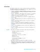
N5416A USB 2.0 Compliance Test Option Notes on Electrical Testing 7 Low and Full Speed Tests Droop/Drop Test 178 Inrush Current Test 197 Signal Integrity Test 200 Back-Voltage Test Before Enumerate 221 Back-Voltage Test After Enumerate 224 100 mA Load 51W, 2% Vbus D- NC D+ NC GND 10µF, 20% Figure 4 100 mA Load Board Schematic 500 mA Load 10W, 5% Vbus D- NC D+ NC GND 4.
7 Low and Full Speed Tests Droop/Drop Test The Drop test is a measure of a hub’s ability to host full load current while keeping the output voltage above spec. To perform this test, VBUS is measured with all downstream ports loaded with 500 mA loads (for host and self powered hubs) or 100 mA loads (for bus powered hubs). The lowest value measured across all ports must be between 4.75 V and 5.25 V for host and self powered hubs or it must be greater than or equal to 4.4 V for bus powered hubs.
Low and Full Speed Tests USB Power 7 DS1 There are several switches/buttons that are used for general control of the test fixture. These include (see picture below): • Switch S5 allows you to select either the Droop or Drop test. • Switch S4 allows you to select either the 100 mA or 500 mA load. • Press and hold S1 for at least three seconds to turn the test fixture on. • While pressing and holding S2, press S1 to turn the test fixture off.
7 Low and Full Speed Tests Host and Self-Powered Hubs Equipment Used dededededededede Table 33 Equipment Used in Host and Self-Powered Hubs Droop/Drop Tests Quantity Item Description/Model 1 Oscilloscope Agilent 5485xA, 9000A Series, 80000 or 90000A Series, 54831B/D, or 54832B/D 2 Passive or active probes For 5485x, 9000A Series, 80000 and 90000A Series oscilloscopes: • Agilent E2697A with 10073C, or 1156A For 54831B/D and 54832B/D oscilloscopes: • Agilent 1165A 1 Digital Multimeter (DMM) Agil
7 Low and Full Speed Tests Configuring the Tests Drop Test - Connecting and Using the New E2649-66405 Droop/Drop Test Fixture 1 For 54831B/D and 54832B/D oscilloscopes, use 1165A passive probes. For the 5485XA, 80000, and 90000A Series oscilloscopes, use E2697A high- impendance converter with 10:1 passive probes, or 1156A active probes. The picture after Step 12 shows the connection setup. 2 Click on the Set Up tab and check the New DroopDrop Fixture box.
7 Low and Full Speed Tests 3 Under the Select Tests tab, check the box next to Droop/Drop Test. 4 Click on the Configure tab and scroll to the bottom of the left pane. There will be several listings under the Droop/Drop Test entry that allow you to configure your tests. Set these to the appropriate values for your specific testing conditions. 5 The new E2649- 66405 Droop/Drop test fixture supports both manual and automatic testing.
7 Low and Full Speed Tests 6 To configure the fixture for drop testing, switch S5 to the drop mode position. 7 Select the 500 mA current load by using the S4 switch. 8 Press and hold S1 until the 7- segment LED test port indicator lights up. The test fixture is now turned on. 9 U7 will illuminate with a zero, indicating the initial state. This allows you to make the Vno_load measurement for port 0.
7 Low and Full Speed Tests Droop Test -Connecting and Using the New E2649-66405 Droop/Drop Test Fixture 1 For 54831B/D and 54832B/D oscilloscopes, use 1165A passive probes. For the 5485XA, 80000, and 90000A Series oscilloscopes, use E2697A high- impendance converter with 10:1 passive probes, or 1156A active probes. The picture after Step 12 shows the connection setup. 2 Click on the Set Up tab and check the New DroopDrop Fixture box.
7 Low and Full Speed Tests 3 Under the Select Tests tab, check the box next to Droop/Drop Test. 4 Click on the Configure tab and scroll to the bottom of the left pane. There will be several listings under the Droop/Drop Test entry that allow you to configure your tests. Set these to the appropriate values for your specific testing conditions. 5 The new E2649- 66405 Droop/Drop test fixture supports both manual and automatic testing.
7 Low and Full Speed Tests Connecting the Equipment (if you do not have the new E2649- 66405 Droop/Drop Test Fixture) The USB automated test application will prompt you to perform these connection steps: 1 For 54831B/D and 54832B/D oscilloscopes, use 1165A passive probes. For the 5485XA, 80000 and 90000A Series oscilloscpes, use E2697A high- impedance converter with 10:1 passive probes, or 1156A active probes.
7 Low and Full Speed Tests 5 Connect the Channel 2 probe to the Vbus test point on the load board connected adjacent to the USB port to be measured. This provides the oscilloscope trigger. 6 Check I have completed these instructions. Running the Tests 1 Click Run Tests. Test Instructions The USB automated test application will prompt you to perform these steps: 1 For 54831B/D and 54832B/D oscilloscopes, use 1165A passive probes.
7 Low and Full Speed Tests Bus-Powered Hubs Equipment Used 1 Table 34 Equipment Used in Bus-Powered Hubs Droop/Drop Tests Quantity Item Description/Model 1 Oscilloscope Agilent 5485xA Series, 9000A Series, 80000 or 90000A Series, 54831B/D, or 54832B/D 2 Passive or active probes For 5485x, 9000 SeriesA, 80000 and 90000A Series oscilloscopes: • Agilent E2697A with 10073C, or 1156A For 54831B/D and 54832B/D oscilloscopes: • Agilent 1165A 1 Droop/Drop test fixture Agilent E2649-66405 1 Digital M
7 Low and Full Speed Tests Configuring the Tests Drop Test - Connecting and Using the New E2649-66405 Droop/Drop Test Fixture 1 For 54831B/D and 54832B/D oscilloscopes, use 1165A passive probes. For the 5485XA, 9000A Series, 80000, and 90000A Series oscilloscopes, use E2697A high- impendance converter with 10:1 passive probes, or 1156A active probes. The picture after Step 12 shows the connection setup. 2 Click on the Set Up tab and check the New DroopDrop Fixture box.
7 Low and Full Speed Tests 3 Under the Select Tests tab, check the box next to Droop/Drop Test. 4 Click on the Configure tab and scroll to the bottom of the left pane. There will be several listings under the Droop/Drop Test entry that allow you to configure your tests. Set these to the appropriate values for your specific testing conditions. 5 The new E2649- 66405 Droop/Drop test fixture supports both manual and automatic testing.
7 Low and Full Speed Tests 6 To configure the fixture for drop testing, switch S5 to the drop mode position. 7 Select the 100 mA current load by using the S4 switch. 8 Press and hold S1 until the 7- segment LED test port indicator lights up. The test fixture is now turned on. 9 U7 will illuminate with a zero, indicating the initial state. This allows you to make the Vno_load measurement for port 0.
7 Low and Full Speed Tests Droop Test -Connecting and Using the New E2649-66405 Droop/Drop Test Fixture 1 For 54831B/D and 54832B/D oscilloscopes, use 1165A passive probes. For the 5485XA, 80000, and 90000A Series oscilloscopes, use E2697A high- impendance converter with 10:1 passive probes, or 1156A active probes. 2 Click on the Set Up tab and check the New DroopDrop Fixture box. Also click on the Droop Drop Ports button and select the test ports you want to use on the fixture.
7 Low and Full Speed Tests 3 Under the Select Tests tab, check the box next to Droop/Drop Test. 4 Click on the Configure tab and scroll to the bottom of the left pane. There will be several listings under the Droop/Drop Test entry that allow you to configure your tests. Set these to the appropriate values for your specific testing conditions. 5 The new E2649- 66405 Droop/Drop test fixture supports both manual and automatic testing.
7 Low and Full Speed Tests Connecting the Equipment (if you do not have the E2649-66405 Droop/Drop Test Fixture) The USB automated test application will prompt you to perform these connection steps: 1 For 54831B/D and 54832B/D oscilloscopes, use 1165A passive probes. For the 5485XA, 80000 and 90000A Series oscilloscpes, use E2697A high- impedance converter with 10:1 passive probes, or 1156A active probes. 2 Connect 100mA load boards to all but the adjacent port on the bus- powered hub under test.
7 Low and Full Speed Tests 4 Connect the Channel 1 probe to Vbus on the SQiDD board with the probe's ground to GND on one of the 100mA load boards. This is the port under test. 5 Connect the Channel 2 probe to the Vbus test point on the load board connected adjacent to the USB port to be measured. This provides the oscilloscope trigger. 6 Check I have completed these instructions. Running the Tests 1 Click Run Tests.
7 Low and Full Speed Tests 4 Connect the Channel 1 probe to Vbus on the SQiDD board with the probe's ground to GND on one of the 100 mA load boards. This is the port under test. 5 Connect the Channel 2 probe to the Vbus test point on the load board connected adjacent to the USB port to be measured. This provides the oscilloscope trigger. 6 Click OK to close the Test Instructions dialog. Viewing Test Results 1 When the Testing Complete dialog appears, click OK. The Results tab shows the test results.
7 Low and Full Speed Tests Inrush Current Test Equipment Used Table 35 Equipment Used in Inrush Current Test Quantity Item Description/Model 1 Oscilloscope Agilent 5485xA Series, 80000 or 90000A Series, 54831B/D, or 54832B/D 1 Current probe For 5485x, 80000 and 90000A Series oscilloscopes: • Agilent E2697A high impedance converter, N2774A current probe, and N2775A power supply For 54831B/D and 54832B/D oscilloscopes: • Agilent 1147A 1 Digital Multimeter (DMM) Agilent 34401A or equivalent 1 SQi
7 Low and Full Speed Tests Configuring the Tests Connecting the Equipment The USB automated test application will prompt you to perform these connection steps: 1 Attach the current probe: For the 54831B/D or 54832B/D oscilloscope, attach the 1147A current probe to the oscilloscope's Channel 4 input. For the 54853A, 54854A, 54855A oscilloscope: a Attach the E2697A high- impedance connector to the Channel 4 input. b Attach the N2774A current probe to the E2697A.
Low and Full Speed Tests 7 Running the Tests 1 Click Run Tests. Test Instructions, Part 1 The USB automated test application will prompt you to perform these steps: 1 Attach the current probe to the current loop on the SQiDD board with the arrow on the probe toward the device under test. 2 Attach the device under test to the SQiDD board. 3 Place the switch on the SQiDD board to the discharge position (opposite the ON position) . 4 Disconnect the device under test from the SQiDD board.
7 Low and Full Speed Tests Signal Integrity Test Host Downstream Signal Quality Test Host Low Speed Test Equipment Used Table 36 Equipment Used in Host Downstream Low Speed Signal Quality Test Quantity Item Description/Model 1 Oscilloscope Agilent 5485xA Series, 80000 or 90000A Series, 54831B/D, or 54832B/D 2 Passive or active probes For 5485x, 80000 and 90000A Series oscilloscopes: • Agilent E2697A with 10073C, or 1156A For 54831B/D and 54832B/D oscilloscopes: • Agilent 1165A 1 Host test bed com
7 Low and Full Speed Tests Configuring the Tests Make sure you set the Test Type configuration option to “Low- Speed Near End” before running the test. Connecting the Equipment The USB automated test application will prompt you to perform these connection steps: 1 For 54831B/D and 54832B/D oscilloscopes, use 1165A passive probes. For the 5485XA, 80000 and 90000A Series oscilloscpes, use E2697A high- impedance converter with 10:1 passive probes, or 1156A active probes.
7 Low and Full Speed Tests Running the Tests 1 Click Run Tests. Viewing Test Results 1 When the Testing Complete dialog appears, click OK. The Results tab shows the test results.
7 Low and Full Speed Tests Selecting the Tests Connecting the Equipment The USB automated test application will prompt you to perform these connection steps: 1 For 54831B/D and 54832B/D oscilloscopes, use 1165A passive probes. For the 5485XA, 80000 and 90000A Series oscilloscpes, use E2697A high- impedance converter with 10:1 passive probes, or 1156A active probes. 2 Attach the passive probes to the oscilloscope's Channel 3 and Channel 2 inputs.
7 Low and Full Speed Tests 7 Check I have completed these instructions. Running the Tests 1 Click Run Tests. Viewing Test Results 1 When the Testing Complete dialog appears, click OK. The Results tab shows the test results.
7 Low and Full Speed Tests Hub Downstream Signal Quality Test Hub Downstream Low Speed Test Equipment Used Table 38 Equipment Used in Hub Downstream Low Speed Signal Quality Test Quantity Item Description/Model 1 Oscilloscope Agilent 5485xA Series, 80000 or 90000A Series, 54831B/D, or 54832B/D 2 Passive or active probes For 5485x, 80000 and 90000A Series oscilloscopes: • Agilent E2697A with 10073C, or 1156A For 54831B/D and 54832B/D oscilloscopes: • Agilent 1165A 1 Host test bed computer Any com
7 Low and Full Speed Tests Configuring the Tests Make sure you set the Test Type configuration option to “Low- Speed Near End” before running the test. Connecting the Equipment The USB automated test application will prompt you to perform these connection steps: 1 For 54831B/D and 54832B/D oscilloscopes, use 1165A passive probes. For the 5485XA, 80000 and 90000A Series oscilloscpes, use E2697A high- impedance converter with 10:1 passive probes, or 1156A active probes.
Low and Full Speed Tests 7 8 Check I have completed these instructions. Running the Tests 1 Click Run Tests. Viewing Test Results 1 When the Testing Complete dialog appears, click OK. The Results tab shows the test results.
7 Low and Full Speed Tests Hub Downstream Full Speed Test Equipment Used Table 39 Equipment Used in Hub Downstream Full Speed Signal Quality Test Quantity Item Description/Model 1 Oscilloscope Agilent 5485xA Series, 80000 or 90000A Series, 54831B/D, or 54832B/D 2 Passive or active probes For 5485x, 80000 and 90000A Series oscilloscopes: • Agilent E2697A with 10073C, or 1156A For 54831B/D and 54832B/D oscilloscopes: • Agilent 1165A 1 Host test bed computer Any computer with hi-speed USB ports 1
7 Low and Full Speed Tests Connecting the Equipment The USB automated test application will prompt you to perform these connection steps: 1 For 54831B/D and 54832B/D oscilloscopes, use 1165A passive probes. For the 5485XA, 80000 and 90000A Series oscilloscpes, use E2697A high- impedance converter with 10:1 passive probes, or 1156A active probes. 2 Attach the passive probes to the oscilloscope's Channel 3 and Channel 2 inputs. 3 Attach the SQiDD board to the hub under test.
7 Low and Full Speed Tests 8 Check I have completed these instructions. Running the Tests 1 Click Run Tests. Viewing Test Results 1 When the Testing Complete dialog appears, click OK. The Results tab shows the test results.
7 Low and Full Speed Tests Upstream Signal Quality Test Upstream Low Speed Test Equipment Used Table 40 Equipment Used in Upstream Low Speed Signal Quality Test Quantity Item Description/Model 1 Oscilloscope Agilent 5485xA Series, 80000 or 90000A Series, 54831B/D, or 54832B/D 3 Passive or active probes For 5485x, 80000 and 90000A Series oscilloscopes: • Agilent E2697A with 10073C, or 1156A For 54831B/D and 54832B/D oscilloscopes: • Agilent 1165A 1 Host test bed computer Any computer with hi-spee
7 Low and Full Speed Tests Configuring the Tests Make sure you set the Test Type configuration option to “Low- Speed Far End” before running the test. Connecting the Equipment The USB automated test application will prompt you to perform these connection steps: 1 For 54831B/D and 54832B/D oscilloscopes, use 1165A passive probes. For the 5485XA, 80000 and 90000A Series oscilloscpes, use E2697A high- impedance converter with 10:1 passive probes, or 1156A active probes.
Low and Full Speed Tests 7 7 Check I have completed these instructions. Running the Tests 1 Click Run Tests.
7 Low and Full Speed Tests Test Instructions The USB automated test application will prompt you to perform these steps: 1 Invoke the HS Electrical Test Tool software on the Hi- Speed Electrical Test Bed computer. Select Device and click the [TEST] button to enter the Device Test menu. 2 On the Device Test Menu of the HS Electrical Test Tool software, click [Enumerate Bus] once. All devices attached to the host controller should appear in the device enumeration list.
Low and Full Speed Tests 7 5 Click OK to close the Test Instructions dialog. Viewing Test Results 1 When the Testing Complete dialog appears, click OK. The Results tab shows the test results.
7 Low and Full Speed Tests Upstream Full Speed Test Equipment Used Table 41 Equipment Used in Upstream Full Speed Signal Quality Test Quantity Item Description/Model 1 Oscilloscope Agilent 5485xA Series, 80000 or 90000A Series, 54831B/D, or 54832B/D 3 Passive or active probes For 5485x, 80000 and 90000A Series oscilloscopes: • Agilent E2697A with 10073C, or 1156A For 54831B/D and 54832B/D oscilloscopes: • Agilent 1165A 1 Host test bed computer Any computer with hi-speed USB ports 1 SQiDD boar
7 Low and Full Speed Tests Connecting the Equipment The USB automated test application will prompt you to perform these connection steps: 1 For 54831B/D and 54832B/D oscilloscopes, use 1165A passive probes. For the 5485XA, 80000 and 90000A Series oscilloscpes, use E2697A high- impedance converter with 10:1 passive probes, or 1156A active probes. 2 Attach the passive probes to the oscilloscope's channel Channel 2, Channel 3 and Channel 1 inputs.
7 Low and Full Speed Tests 7 Check I have completed these instructions. Running the Tests 1 Click Run Tests.
7 Low and Full Speed Tests Test Instructions The USB automated test application will prompt you to perform these steps: 1 Invoke the HS Electrical Test Tool software on the Hi- Speed Electrical Test Bed computer. Select Device and click the [TEST] button to enter the Device Test menu. 2 On the Device Test Menu of the HS Electrical Test Tool software, click [Enumerate Bus] once. All devices attached to the host controller should appear in the device enumeration list.
7 Low and Full Speed Tests 5 Click OK to close the Test Instructions dialog. Viewing Test Results 1 When the Testing Complete dialog appears, click OK. The Results tab shows the test results.
Low and Full Speed Tests 7 Back-Voltage Test Before Enumerate Equipment Used Table 42 Equipment Used in Back-Voltage Test Quantity Item Description/Model 1 Digital Multimeter (DMM) Agilent 34401A or equivalent 1 SQiDD board or back-voltage test fixture Agilent E2646A/B 1 1 meter USB cable Any listed on USB-IF web site Selecting the Tests Notes on USB Electrical Compliance Testing 221
7 Low and Full Speed Tests Configuring the Tests Connecting the Equipment The USB automated test application will prompt you to perform these connection steps: 1 Connect power supply to device/hub under test, and connect the device/hub upstream port to the SQiDD board using a known good USB cable. 2 Check I have completed these instructions. Running the Tests 1 Click Run Tests.
7 Low and Full Speed Tests DThe USB automated test application will prompt you to: measure the voltage between D- and Gnd on the SQiDD board and record the value. Viewing Test Results 1 When the Testing Complete dialog appears, click OK. The Results tab shows the test results.
7 Low and Full Speed Tests Back-Voltage Test After Enumerate Equipment Used Table 43 Equipment Used in Back-Voltage Test Quantity Item Description/Model 1 Digital Multimeter (DMM) Agilent 34401A or equivalent 1 SQiDD board or back-voltage test fixture Agilent E2646A/B 1 1 meter USB cable Any listed on USB-IF web site Selecting the Tests Configuring the Tests Connecting the Equipment The USB automated test application will prompt you to perform these connection steps: 1 Connect power supply to
7 Low and Full Speed Tests cable from the host. Connect the device/hub upstream port to the SQiDD board using a known good USB cable. 2 Check I have completed these instructions. Running the Tests 1 Click Run Tests. Test Instructions VBUS The USB automated test application will prompt you to: measure the voltage between Vbus and Gnd on the SQiDD board and record the value.
7 Low and Full Speed Tests Viewing Test Results 1 When the Testing Complete dialog appears, click OK. The Results tab shows the test results.
N5416A USB 2.0 Compliance Test Option Notes on Electrical Testing 8 On-The-Go Electrical Tests Equipment Used 228 Installing the USB-OET (OTG Electrical Test) Fixture Driver 229 Selecting the Tests 229 Configuring the Tests 230 Connecting the Equipment 230 Running the Tests 231 Viewing Test Results 233 All of the On- The- Go electrical tests use the same test setup.
8 On-The-Go Electrical Tests Equipment Used Table 44 Equipment Used in On-The-Go Electrical Tests Quantity Item Description/Model 1 Oscilloscope Agilent 5485xA Series, 9000A Series, 80000 or 90000A Series, 54831B/D, or 54832B/D 2 Passive or active probes For 5485x, 80000 and 90000A Series oscilloscopes: • Agilent 1156A For 54831B/D and 54832B/D oscilloscopes: • Agilent 1165A 1 Digital Multimeter (DMM) Agilent 34401A or equivalent 1 USB OTG test fixture Agilent N5417A 1 Power supply Agilent
On-The-Go Electrical Tests 8 Installing the USB-OET (OTG Electrical Test) Fixture Driver 1 Plug the OET fixture to any USB port. 2 A Found New Hardware Wizard window will pop up (Windows XP). 3 Select Install the software automatically from the wizard window.
8 On-The-Go Electrical Tests Configuring the Tests If the power supply’s SICL address is different from the default, make sure you set the E3631A Instrument Address configuration option to the power supply’s SICL address. Connecting the Equipment The USB automated test application will prompt you to perform these connection steps: N O TE Note: For 54831B/D and 54832B/D oscilloscopes, use 1165A passive probes. For the 5485XA, 80000 and 90000A Series oscilloscpes, use 1156A active probes.
On-The-Go Electrical Tests 8 9 Connect the E3631A power supply to the oscilloscope using the 82357A USB/GPIB Interface. 10 Connect the OET test fixture to the oscilloscope's USB port . 11 Check I have completed these instructions. Running the Tests 1 Click Run Tests. E1 E8 A-Device Output Voltage 1 Set the OET switches to the following settings.
8 On-The-Go Electrical Tests E3 VBUS Rise Time 1 Set the OET switches to the following settings. E5 B-Device (SRP capable) to OTG Device Output Voltage 1 Set the OET switches to the following settings. E6 B-Device (SRP capable) to Host Output Voltage 1 Set the OET switches to the following settings. E19 A-Device Session Valid 1 Set the OET switches to the following settings.
On-The-Go Electrical Tests 8 E20 B-Device VBUS Valid 1 Set the OET switches to the following settings. E22 Data-Line Pulsing Test 1 Set the OET switches to the following settings. A-Device VBUS Valid (VA_VBUS_VLD) 1 Set the OET switches to the following settings. E1 E2 A-Device VBUS Valid (VMin) E1 E2 A-Device VBUS Valid (VMean) Viewing Test Results 1 When the Testing Complete dialog appears, click OK. The Results tab shows the test results.
8 234 On-The-Go Electrical Tests Notes on USB Electrical Compliance Testing
Index Numerics 100 mA load board schematic, 177 10073C miniature passive probes, 26 1156A probes, 26 500 mA load board schematic, 177 81134A pulse generator, 98 81134A/81130A Instrument Address configuration option, 66, 98 82357A GPIB-USB converter, 98 82357A USB/GPIB interface, 21 C cables, 21 calibrate probes, 26 calibration, 26 common ground reference, 26 compensate passive probes, 26 computer, high-speed electrical test bed, 22 configure, 29 connect, 29 D Data Eye Test Mode configuration option, 175 d
Index S select tests, 29 SICL address, power supply, 230 SICL address, pulse generator, 66, 98 software, installing, 16 SQiDD board, 23 starting the USB automated test application, 28 T test bed computer, high-speed electrical, 22 test fixtures, USB electrical, 24 Test Type configuration option, 201, 206, 212 tests, running, 31 Threshold configuration option, 176 Trigger Level configuration option, 176 troubleshooting hi-speed test failures, 175 U upstream signal quality test, 211 USB automated testing—a