
Technical data

Service Guide N5230-90025 3-23
PNA Series Microwave Network Analyzers Tests and Adjustments
N5230C System Verification
Cable Substitution
The test port cables specified for the network analyzer system have been characterized for connector
repeatability, magnitude and phase stability with flexing, return loss, insertion loss, and aging rate. Since
test port cable performance is a significant contributor to the system performance, cables of lower
performance will increase the uncertainty of your measurement. Refer to the plots in the cable tests (earlier
in this chapter) that show the performance of good cables. It is highly recommended that the test port
cables be regularly tested.
If the system verification is performed with a non-Agilent cable, ensure that the cable meets or exceeds the
specifications for the test cable specified in the previous table, “Equipment Used in the System Verification
Procedure.” Refer to the cable’s user’s guide for specifications.
Kit Substitution
Non-Agilent calibration kits and verification kits are not recommended nor supported.
System Verification Procedure
1. If you desire printed test outputs, connect a printer to the analyzer. For the printer, ensure that the
correct driver is loaded and the printer is defined as the default printer. Refer to the embedded help in the
analyzer for printer setup. Let the analyzer warm up for at least 90 minutes.
2. Insert the verification kit disk into the analyzer disk drive.
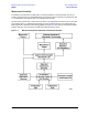
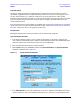
3. On the System menu, point to Service, and then click System Verification. The System Verification
dialog box is displayed; refer to Figure 3-9.
Figure 3-9 System Verification Dialog Box
4. In the Calibration Kit box, select the calibration kit or electronic calibration module (ECal) that is being
used by clicking on it. The corresponding verification kit to use is selected for you and displayed in the