
Technical data

8-10 Service Guide N5230-90025
General Purpose Maintenance Procedures PNA Series Microwave Network Analyzers
Error Terms N5230C
Error Term Data
The error term descriptions in this section include the following information:
• a table of the error terms
• description and significance of each error term
• measurements affected by each error term
• typical cause of failure for each error term
The same description applies to both the forward (F) and reverse (R) terms.
IMPORTANT Data are listed here as a convenience only. Detailed instrument specifications are listed in
the embedded help in the network analyzer.
If Error Terms Seem Worse than Expected
To verify that the system still conforms to specifications, perform a system verification. Refer to Chapter 3,
“Tests and Adjustments”.
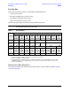
Tabl e 8-1 Er ror Term D ata
a
a. The data in this table are uncorrected system performance. The values apply over an environmental temperature range
of 25 °C ±5 °C, with less than 1 °C deviation from the calibration temperature.
Parameter
Frequency Range
300 kHz
to
10 MHz
b
b. All values for 300 kHz to 10 MHz are typical.
10 MHz
to
1 GHz
1 GHz
to
3 GHz
3 GHz
to
5 GHz
5 GHz
to
10.5 GHz
10.5 GHz
to
11.5 GHz
11.5 GHz
to
13.5 GHz
13.5 GHz
to
16 GHz
16 GHz
to
20 GHz
Directivity –23dB –28dB –25dB –20dB –17dB –15dB
Source
Match
–8dB –12dB –12dB –12dB –12dB –10dB –8dB
Load Match –9dB –20dB –20dB –18dB –12dB –7 dB –7.5dB
Parameter
300 kHz
to
5 MHz
5 MHz
to
10 MHz
10 MHz
to
45 MHz
45 MHz
to
4 GHz
4 GHz
to
6 GHz
6 GHz
to
10.5 GHz
10.5 GHz
to
13.5 GHz
13.5 GHz
to
15 GHz
15 GHz
to
20 GHz
Crosstalk
c
c. All crosstalk values are typical. Measurement conditions: normalized to a thru, measured with two shorts, 10 Hz IF
bandwidth, averaging factor of 8, alternate mode, source power set to the lesser of the maximum power out or the
maximum receiver power.
–70dB –100dB –110dB –122dB –123dB –120dB –115dB –110dB