
Technical data

Service Guide N5230-90025 7-53
PNA Series Microwave Network Analyzers Repair and Replacement Procedures
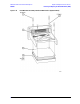
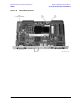
N5230C Removing and Replacing the Midweb and the B1 Fan
Removing and Replacing the Midweb and the B1 Fan
Tools Required
• T-10 TORX driver (set to 9 in-lb)
• T-20 TORX driver (set to 21 in-lb)
• Pozidriv screw driver
• 5/16 inch open-end torque wrench (set to 10 in-lb)
• ESD grounding wrist strap
Removal Procedure
1. Disconnect the power cord.
2. Remove the front panel assembly. Refer to “Removing and Replacing the Front Panel Assembly” on page
7-8.
3. Remove the outer and inner covers. Refer to “Removing the Covers” on page 7-6.
4. Remove the A22 test port coupler. This is necessary to gain access to one of the midweb mounting
screws. Refer to “Removing and Replacing the A21, A22, A23, and A24 Test Port Couplers and Coupler
Mounting Blocks” on page 7-38.
5. Remove the A19 MASSQuad and the MASS mounting block. This is necessary to gain access to one of
the midweb mounting screws. Refer to “Removing and Replacing the A19 MASS 26.5 (MASSQuad) and
MASSQuad Mounting Block” on page 7-34.
6. Remove the A4 power supply assembly. Refer to “Removing and Replacing the A4 Power Supply
Assembly” on page 7-14.
7. Remove the card cage boards (A5 through A10) and plenum bracket. Refer to “Removing and Replacing
the A5 through A10 Boards” on page 7-16.
8. Remove the second source boards (A11, A12, A13, and A17). Refer to “Removing and Replacing the A12
Multiplier and the A13 Fractional-N Synthesizer Boards” on page 7-20.
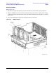
NOTE This procedure has two parts: removing the midweb and removing the fan from the midweb.
You must remove the midweb before removing the fan.