
Technical data


7-44 Service Guide N5230-90025
Repair and Replacement Procedures PNA Series Microwave Network Analyzers
Removing and Replacing the A29 Reference Switch, Limiter, and DC Block N5230C
Removing and Replacing the A29 Reference Switch, Limiter, and DC Block
Tools Required
• T-10 TORX driver (set to 9 in-lb)
• T-20 TORX driver (set to 21 in-lb)
• 1/4 inch open-end wrench
• 5/16 inch open-end wrench
• 5/16 inch open-end torque wrench (set to 10 in-lb)
• ESD grounding wrist strap
Removal Procedure
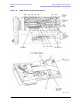
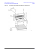
Refer to Figure 7-19 for this procedure.
1. Disconnect the power cord.
2. Remove the outer and inner covers. Refer to “Removing the Covers” on page 7-6.
3. Remove the A29 reference switch (and bracket if necessary):
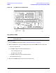
a. Disconnect the A29 reference switch cable from the A17 QABC board at A17J10. This connector can
be accessed from the right side of the analyzer. Refer to Figure 7-12 on page 7-31 for location of this
cable connector.
b. Disconnect cables W66, W67, and W68.
c. Remove two screws (item
①
) and remove the A29 reference switch.
d. To remove the A29 reference switch bracket, remove three screws (item
➁).
4. Remove the DC block and limiter:
a. Disconnect cable W69 from the DC block.
a. While holding the hex nut on cable W68 with a 1/4-in wrench, use a 5/16-in wrench to disconnect
this cable from the limiter.
b. Cut the cable tie used to secure the limiter and remove the DC block and limiter from the analyzer.
c. Using a 5/16-in wrench to hold the hex nut on the limiter, use another 5/16-in wrench to loosen the
DC block connector and remove the DC block from the limiter.
Replacement Procedure
1. Reverse the order of the removal procedure using the tools specified. Be sure to install a new cable tie to
secure the limiter.
2. Perform the post-repair adjustments, verifications, and performance tests that pertain to this removal
procedure. Refer to Table 7-2 on page 7-58.