
Technical data


7-42 Service Guide N5230-90025
Repair and Replacement Procedures PNA Series Microwave Network Analyzers
Removing and Replacing the A26 60-dB Source Step Attenuator N5230C
Removing and Replacing the A26 60-dB Source Step Attenuator
Tools Required
• T-10 TORX driver (set to 9 in-lb)
• T-20 TORX driver (set to 21 in-lb)
• 5/16 inch open-end torque wrench (set to 10 in-lb)
• ESD grounding wrist strap
Removal Procedure
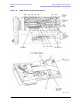
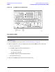
Refer to Figure 7-18 for this procedure.
1. Disconnect the power cord.
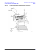
2. Remove the outer and inner covers. Refer to “Removing the Covers” on page 7-6.
3. Remove the A17 QABC board. Refer to “Removing and Replacing the A17 QABC Board” on page 7-30.
4. Remove the A26 step attenuator from the A17 QABC board:
a. Disconnect cables W76, W78, and W79 from the A26 step attenuator.
b. Remove the two mounting screws, located on the other side of the A17 QABC board, and remove the
A26 step attenuator from the A17 QABC board.
Replacement Procedure
1. Reverse the order of the removal procedure.
Use the tools specified for all cable connections and mounting screws.
2. Perform the post-repair adjustments, verifications, and performance tests that pertain to this removal
procedure. Refer to Table 7-2 on page 7-58.