
Technical data


7-20 Service Guide N5230-90025
Repair and Replacement Procedures PNA Series Microwave Network Analyzers
Removing and Replacing the A12 Multiplier and the A13 Fractional-N Synthesizer Boards N5230C
Removing and Replacing the A12 Multiplier and the A13 Fractional-N
Synthesizer Boards
Tools Required
• T-10 TORX driver (set to 9 in-lb)
• T-20 TORX driver (set to 21 in-lb)
• 5/16 inch open-end torque wrench (set to 10 in-lb)
• ESD grounding wrist strap
Removal Procedure
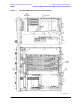
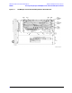
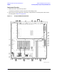
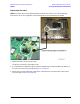
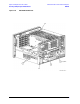
Refer to Figure 7-8 for this procedure.
1. Disconnect the power cord.
2. Remove the outer and inner covers. Refer to “Removing the Covers” on page 7-6.
3. The A13 fractional-N synthesizer board must be removed before the A12 multiplier board can be
removed.
4. Remove the A13 fractional-N synthesizer board:
a. Disconnect cable W73 from the A17 QABC board. This cable is attached to the bottom of the A13
fractional-N synthesizer board.
b. Remove jumper cables W61 and W62 and slide the A13 fractional-N synthesizer board out of the
analyzer being careful not to damage any adjacent components.
5. Remove the A12 multiplier board:
a. Disconnect cable W63 and, while holding this cable out of the way, slide the A12 multiplier board out
of the analyzer. Be careful not to over bend the W63 cable.
Replacement Procedure
1. Reverse the order of the removal procedure. Be especially careful not to damage cable W63.
Use the tools specified for all cable connections and mounting screws.
2. Perform the post-repair adjustments, verifications, and performance tests that pertain to this removal
procedure. Refer to Table 7-2 on page 7-58.