
Technical data

7-18 Service Guide N5230-90025
Repair and Replacement Procedures PNA Series Microwave Network Analyzers
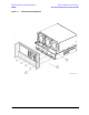
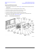
Removing and Replacing the A11 Vertical Motherboard and the Plenum Bracket N5230C
Removing and Replacing the A11 Vertical Motherboard and the Plenum Bracket
Tools Required
• T-10 TORX driver (set to 9 in-lb)
• T-20 TORX driver (set to 21 in-lb)
• ESD grounding wrist strap
Removal Procedure
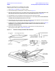
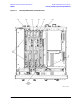
Refer to Figure 7-7 for this procedure.
1. Disconnect the power cord.
2. Remove the outer and inner covers. Refer to “Removing the Covers” on page 7-6.
3. Remove the A12 multiplier and A13 fractional-N synthesizer boards. Refer to “Removing and Replacing
the A12 Multiplier and the A13 Fractional-N Synthesizer Boards” on page 7-20.
4. Remove the A17 QABC board. Refer to “Removing and Replacing the A17 QABC Board” on page 7-30.
5. Remove the A11 vertical motherboard:
a. Remove the six mounting screws (item
①
) from the A11 vertical motherboard.
b. Lift the A11 vertical motherboard out of the A14 system motherboard connector and remove it from
the analyzer.
6. Remove the plenum bracket:
a. Remove the two screws (item
➁) holding the plenum bracket in place.
b. Remove the plenum bracket from the analyzer.
Replacement Procedure
1. Reverse the order of the removal procedure. If the plenum bracket was removed, reinstall it first and
leave the attachment screws loose until the A11 vertical motherboard has been securely fastened.
Use the tools specified for all mounting screws.
2. Perform the post-repair adjustments, verifications, and performance tests that pertain to this removal
procedure. Refer to Table 7-2 on page 7-58.