
Technical data

7-16 Service Guide N5230-90025
Repair and Replacement Procedures PNA Series Microwave Network Analyzers
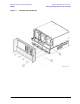
Removing and Replacing the A5 through A10 Boards N5230C
Removing and Replacing the A5 through A10 Boards
Tools Required
• T-10 TORX driver (set to 9 in-lb)
• T-20 TORX driver (set to 21 in-lb)
• ESD grounding wrist strap
Removal Procedure
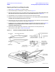
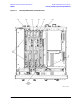
Refer to Figure 7-6 for this procedure.
1. Disconnect the power cord.
2. Remove the outer and inner covers. Refer to “Removing the Covers” on page 7-6.
3. With a T-10 TORX driver, remove the cable hold down wire that secures cables to the top of the midweb
by removing the attachment screw (item
①
).
4. Remove any or all of the A5 through A10 boards:
a. Identify the board you want to remove and disconnect any cables that are attached to it.
NOTE Before removing the board completely, check the bottom of the board for any attached
cables and disconnect them.
b. While holding onto the extractors (item
➁), slide the board out of the slot and remove it from the
analyzer.
Replacement Procedure
1. Reverse the order of the removal procedure. When reinstalling the cable hold down wire, be sure that all
cables are positioned so that they will not be pinched.
Use the tools specified for all cable connections and mounting screws.
2. Perform the post-repair adjustments, verifications, and performance tests that pertain to this removal
procedure. Refer to Table 7-2 on page 7-58.