
Technical data

7-6 Service Guide N5230-90025
Repair and Replacement Procedures PNA Series Microwave Network Analyzers
Removing the Covers N5230C
Removing the Covers
Tools Required
• T-10 TORX driver (set to 9 in-lb)
• T-20 TORX driver (set to 21 in-lb)
Removing the Outer Cover
CAUTION This procedure is best performed with the analyzer resting on its front handles in the vertical
position. Do not place the analyzer on its front panel without the handles. This will damage
the front panel assemblies.
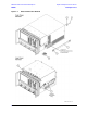
Refer to Figure 7-1. for this procedure.
1. Disconnect the power cord.
2. With a T-20 TORX driver, remove the strap handles (item
①
) by loosening the screws (item ➁) on both
ends until the handle is free of the analyzer.
3. With a T-20 TORX driver, remove the four rear panel feet (item
③
) by removing the center screws (item
④
).
4. Slide the four bottom feet (item
⑤
) off the cover.
5. Slide the cover off of the frame.
Removing the Inner Cover
Refer to Figure 7-1. for this procedure.
1. With a T-10 TORX driver, remove the cover attachment screws (item
⑥
). Some of these screws are flat
head and some are pan head. Note the locations of each type for reinstallation.
2. Options 146 and 246 only: With a T-10 TORX driver, loosen the screws on the two retainer clips (item
⑦
).
3. Lift off the cover.
Replacement Procedure
Reverse the order of the removal procedures.
For Options 146 and 246: Be sure that the cover is located behind the two retainer clips (item
⑦
) before
installing the cover screws (item
⑥
). Remember to tighten the retainer clip screws. The retainer clips may
rotate slightly when the screws are tightened; this is normal and acceptable.