
Technical data

7-4 Service Guide N5230-90025
Repair and Replacement Procedures PNA Series Microwave Network Analyzers
Assembly Replacement Sequence N5230C
Assembly Replacement Sequence
The following steps show the sequence that you should follow to replace an assembly in the network
analyzer.
Step 1. Identify the faulty group. Begin with Chapter 4, “Troubleshooting.”
Step 2. Order a replacement assembly. Refer to Chapter 6, “Replaceable Parts.”
Step 3. Replace the faulty assembly and determine what adjustments are necessary. Refer to
“Post-Repair Procedures” in this chapter.
Step 4. Perform the necessary adjustments. Refer to Chapter 3, “Tests and Adjustments.”
Step 5. Perform the necessary performance tests. Refer to Chapter 3, “Tests and Adjustments.”
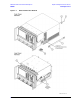
Removal and Replacement Procedures
Table 7-1 List of Procedures
Reference
Designator
Assembly Description Location
None Battery Page 7-56
None Covers, outer and inner Page 7-6
None Front panel USB connector board Page 7-12
None Touchscreen controller board Page 7-10
None Touchscreen display assembly Page 7-13
None Display inverter board Page 7-10
None DC block (Options 146 and 246) Page 7-44
None Front panel assembly Page 7-8
None Limiter (Options 146 and 246) Page 7-44
None Midweb and fans
Page 7-53
None Plenum bracket
Page 7-16
None USB hub board (part of A16 test set motherboard procedure) Page 7-28
A1
A2
A3
Keypad assembly
Display assembly
Front panel interface board
Page 7-10
A4 Power supply assembly Page 7-14
A5
A6, A8
A7, A9
A10
SPAM board
Multiplier boards
Fractional-N synthesizer boards
Frequency reference board
Page 7-16
A11 Vertical motherboard (Options 146 and 246) Page 7-18