
Technical data

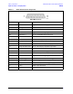

5-18 Service Guide N5230-90025
Theory of Operation PNA Series Microwave Network Analyzers
Signal Separation Group Operation N5230C
Configurable Test Set (Options 145, 146, 245, and 246)
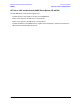
The Option 145, 146, 245, or 246 analyzer allows you to measure devices with higher power and higher
dynamic range limits than the standard analyzer. The theory of operation is the same as for the standard
analyzer except that there are nine front panel SMA jumpers.
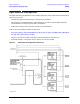
As shown in Figure 5-4 on page 5-19 and in Figure 5-5 on page 5-20, these nine jumpers are installed
between the assemblies listed below.
Four jumpers for all options:
• the A21 test port 1 coupler and the A20 mixer brick channel A
• the A22 test port 2 coupler and the A20 mixer brick channel B
• the A23 test port 3 coupler and the A20 mixer brick channel C
• the A24 test port 4 coupler and the A20 mixer brick channel D
Five additional jumpers for Options 145 and 245:
• the A19 MASSQuad and the A21 test port 1 coupler
• the A19 MASSQuad and the A22 test port 2 coupler
• the A19 MASSQuad and the A23 test port 3 coupler
• the A19 MASSQuad and the A24 test port 4 coupler
• the A19 MASSQuad and the A20 mixer brick channel R
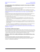
Five additional jumpers for Options 146 and 246:
• the A19 MASSQuad and the A21 test port 1 coupler
• the A19 MASSQuad and the A22 test port 2 coupler
• the A18 MASSQuad and the A23 test port 3 coupler
• the A18 MASSQuad and the A24 test port 4 coupler
• the A29 reference channel switch, limiter, and DC block and the A20 mixer brick channel R
Normal Configurable Test Set Configuration
The normal configurable test set configuration (configurable test set and source step attenuator) is shown
in Figure 5-4 for Options 145 and 245 and in Figure 5-5 for Options 146 and 246.
Options 146 and 246 add a second source, a second attenuator, and a reference channel switch. The A29
reference channel switch provides the capability to select either source 1 or source 2 as the reference
signal. See “A29 Reference Channel Switch, Limiter, and DC Block (Options 146 and 246)” on page 5-22 for
additional information.
With this configuration and inclusion of an external amplifier and accessories, you can calibrate the analyzer
and test devices at power levels up to +30 dBm. You can make measurements in the forward, reverse or both
directions and still achieve these high power levels. For more information on higher power measurements,
search for “Option 014” in the embedded help index in the analyzer.