
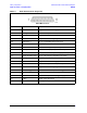
Technical data


5-16 Service Guide N5230-90025
Theory of Operation PNA Series Microwave Network Analyzers
Signal Separation Group Operation N5230C
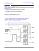
Signal Separation Group Operation
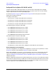
The signal separation group divides the source incident signal into a reference path and a test path. Refer to
Figure 5-3 on page 5-16.
• The reference signal is transmitted to the receiver group as the R input.
• The test signal is transmitted through—and reflected from—the device under test (DUT) and then is
transmitted to the receiver group as the A, B, C, and D inputs.
• Control lines to this group are routed from the A16 test set motherboard.
In this section, the following assemblies are described:
• A19 and A18 (Options 146 and 246) Multiplier/Amplifier/Switch/Splitter 26.5 (MASS 26.5) (MASSQuad)
• A21, A22, A23, and A24 Test Port Couplers
• A25 (Options 145, 245, 146, and 246) and A26 (Options 146 and 246) 60-dB Source Step Attenuator
• Front Panel Jumpers—Configurable Test Set (Options 145, 146, 245, and 246)
Figure 5-3 Standard Test Set Configuration (One Source)