
Technical data


5-6 Service Guide N5230-90025
Theory of Operation PNA Series Microwave Network Analyzers
Synthesized Source Group Operation N5230C
Synthesized Source Group Operation
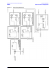
The source group produces a stable output signal by phase locking a synthesized voltage-controlled
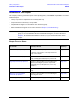
oscillator (VCO). Refer to Table 5-2 on page 5-8 for the full frequency range of the source. The outputs at the
front panel test ports are swept, stepped or CW signals. Maximum leveled output powers are listed in
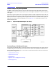
Table 5-1 on page 5-4. For a simple block diagram of the source group, refer to Figure 5-2.
In this section the following are described:
• Basic Operation
• Frequency Offset Operation (Option 080)
• A7, A9, and A13 (Options 146 and 246) Fractional-N Synthesizer Boards
• A6, A8, and A12 (Options 146 and 246) Multiplier Boards
• A19 and A18 (Options 146 and 246) Multiplier/Amplifier/Switch/Splitter 26.5 (MASS 26.5) (MASSQuad)
• A10 Frequency Reference Board (including rear-panel interconnects)
• A16 Test Set Motherboard (including rear-panel interconnects)
• A17 Source 2 ALC and Bias Control (QABC) Board (Options 146 and 246)
Basic Operation
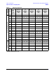
Table 5-2 on page 5-8 lists the L.O. harmonic number, the synthesizer frequencies (A7, A9, and A13), and the
main source frequency (A19 and A18) within the analyzer for each band. This table is referred to throughout
this chapter and also appears on the overall block diagram at the end of Chapter 4, “Troubleshooting.”
The A10 frequency reference board produces a constant phase locked reference signal of 5 MHz that is sent
to the A7, A9, and A13 fractional-N synthesizer boards.
The A7 fractional-N synthesizer board produces an LO signal that is sent through the A6 multiplier to the A20
mixer brick. The frequency is synthesized such that the mixing product of this LO signal with the test signal
output is a constant 7.66 MHz when the spur avoidance function is OFF. With the spur avoidance function ON,
this IF signal is set to various values between 1 and 12 MHz, at source frequencies below 40 MHz, to avoid
generating spurious responses. This IF signal is sent to the A5 SPAM board for digital processing.
The A9 and A13 fractional-N synthesizer boards produce an incident signal that is sent through the A8 or
A12 multiplier board and then the A19 or A18 MASSQuad to the front panel outputs. A portion of this signal
is either split (R channel) or coupled (A, B, C, D channels) off and sent to the A20 mixer brick where it is
mixed with the LO signal from the A6 multiplier board to produce the 7.66 MHz IF signal.
The A7, A9, and A13 fractional-N synthesizer boards each contain their own phase lock circuitry. The A7
board is used to phase lock the LO signal while the A9 and A13 boards are used to phase lock the test
signals (the A9 for source 1 and the A13 for source 2). This makes it possible for the LO signal to be tuned to
a different frequency than the test signal, which is necessary since the LO signal is normally 7.66 MHz
higher than the test signal. Since the A7, A9, and A13 fractional-N synthesizer boards each receive their 5
MHz input reference signal from the exact same source, their outputs remain in-phase even though they are
at different frequencies.