
Technical data


5-4 Service Guide N5230-90025
Theory of Operation PNA Series Microwave Network Analyzers
Network Analyzer System Operation N5230C
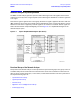
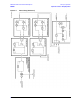
Synthesized Source Group
The built-in synthesized source generates a swept, stepped, or continuous wave (CW) signal in the
frequency ranges as listed in Ta b l e 5 - 1 . The source group provides two signals: an LO signal and an incident
signal. These two signals are normally at the same frequency (except for a 7.66 MHz offset) except for
Option 080, frequency offset mode, where they can be set to different frequencies.
The LO signal is sent directly to the mixers in the receiver group. The incident signal is routed to the front
panel test ports and then to the device under test (DUT) as the test signal. A portion of the incident signal is
either split or coupled off (in the signal separation group) and sent to the mixers in the receiver group as
reference signals. These reference signals are compared (mixed) with the LO signal in the receiver group.
The incident signal output power is leveled by an internal automatic leveling control (ALC) circuit. The
maximum output power level of the network analyzer at the test ports is shown in Ta b l e 5 -1 .
Options 146 and 246 add a second source to the synthesized source group. The primary source (source 1) is
routed to ports 1 and 2 while the secondary source (source 2) is routed to ports 3 and 4. The source 2 signal
path is either functionally the same as or similar to the source 1 signal path. The maximum output power
level for an analyzer with Option 146 or 246 is shown in Tab l e 5 - 1 .
Refer to “Synthesized Source Group Operation” on page 5-6.
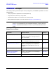
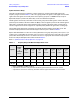
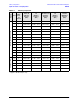
Table 5-1 Frequency Range and Maximum Output Power Level
Options
Nominal
Output
Power
at
Instrument
Preset
Maximum Leveled Output Power
300 kHz
to
10 MHz
a
a. Values for 300 kHz to 10 MHz are typical.
10 MHz
to
4 GHz
4 GHz
to
6 GHz
6 GHz
to
10.5 GHz
10.5 GHz
to
13.5 GHz
13.5 GHz
to
15 GHz
15 GHz
to
20 GHz
140, 240
b
b. Specifications are for Port 1 only; the values shown are typical characteristics for Ports 2, 3, and 4.
–5 dBm +5 dBm +8 dBm +6 dBm +3 dBm 0 dBm 0 dBm –3 dBm
145, 245
b
–8 dBm +5 dBm +8 dBm +6 dBm +1 dBm –2 dBm –2 dBm –8 dBm
146, 246
c
c. Specifications are for Ports 1 and 3 only; the values shown are typical characteristics for Ports 2 and 4.
–8 dBm +5 dBm +8 dBm +6 dBm +1 dBm –2 dBm –2 dBm –8 dBm