
Technical data

4-32 Service Guide N5230-90025
Troubleshooting PNA Series Microwave Network Analyzers
Measurement System Troubleshooting N5230C
6. If the signal is present, reconnect cable W2, and then continue with “Checking the A7 Fractional-N
Synthesizer Output, Band 4” on page 4-32.
Checking the A7 Fractional-N Synthesizer Output, Band 4
Perform this procedure if you observe a problem in band 4 in all receivers.
1. Refer to the block diagram at the back of this chapter and to “Top Cables, All Options Except 146/246” on
page 6-14. Locate semirigid cable W1, at the A7 fractional-N synthesizer board.
CAUTION Be careful not to damage the center pins of the semirigid cable. Some flexing of the cables is
necessary to measure the output. Do not over bend them.
2. Using a 5/16 inch torque wrench, disconnect W1 at A7J106.
3. Connect the spectrum analyzer to A7J106.
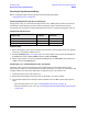
4. Set the network analyzer to a CW frequency of 1 GHz.
• The spectrum analyzer should measure a signal at 1 GHz (plus the 7.66 MHz offset).
5. If this signal is not present, replace the A7 fractional-N synthesizer board. Refer to “Removing and
Replacing the A5 through A10 Boards” on page 7-16.
6. If the signal is present, leave the spectrum analyzer connected to A7J106 and continue with “Checking
the A7 Fractional-N Synthesizer Output, Bands 5 through 17” on page 4-33.