
Technical data

Service Guide N5230-90025 4-31
PNA Series Microwave Network Analyzers Troubleshooting
N5230C Measurement System Troubleshooting
A phase lock problem is due to either:
• faulty RF signal generation (caused by the A10, A9, A8, or A19 board or by the A13, A12, or A18 board for
Options 146 and 246)
• faulty LO signal generation (caused by the A10, A7 or A6 board)
RF Signal Troubleshooting
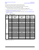
To isolate a broadband RF signal generation failure, check the test port output power:
1. Connect a power meter and power sensor to Port 1 of the analyzer.
2. On the analyzer, press
Preset, set the Center Frequency to 2 GHz, and the Frequency Span to 0 Hz. Note the
power reading displayed on the power meter.
NOTE In the unlocked state, the analyzer will “search” for the reference signal. The output power,
as indicated on the power meter, should be at least 8dBm.
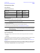
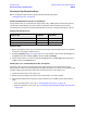
3. Connect the power sensor, in turn, to Ports 2, 3, and 4 and set trace to measure S
22
, S
33
, and S
44
respectively. Note the power reading displayed on the power meter.
If the power level is low or high on only one of the test ports, the problem is in the signal separation group.
Go to “Checking the Signal Separation Group” on page 4-38.
Checking the A10 5 MHz Reference Output, All Bands
1. Refer to the block diagram at the end of this chapter and to “Top Cables, All Options Except 146/246” on
page 6-14. Locate flexible cable W30 (W70 for Option 146 or 246), at the A10 frequency reference board.
2. Disconnect W30 (W70 for Option 146 or 246) from A10J10.
3. Connect the spectrum analyzer to A10J10.
4. The spectrum analyzer should measure a signal at 5 MHz.
5. If the 5 MHz signal is not present, replace the A10 frequency reference board. Refer to “Removing and
Replacing the A5 through A10 Boards” on page 7-16.
6. If the 5 MHz signal is present, reconnect cable W30 (W70 for Option 146 or 246), and then continue
testing at “Checking the A7 Fractional-N Synthesizer Output, Bands 0 through 3” on page 4-31.
Checking the A7 Fractional-N Synthesizer Output, Bands 0 through 3
Perform this procedure if you observe a problem in bands 0 through in all receivers.
1. Refer to the block diagram at the end of this chapter and to “Top Cables, All Options Except 146/246” on
page 6-14. Locate the flexible cable W2, at the A7 fractional-N synthesizer board.
2. Disconnect W2 from A7J101.
3. Connect the spectrum analyzer to A7J101.
4. Set the network analyzer for a 500 MHz CW frequency and observe the spectrum analyzer measurement.
• The spectrum analyzer should measure a signal at 507.66 MHz.
5. If the signal is not present and the 5 MHz reference signal is present from “Checking the A10 5 MHz
Reference Output, All Bands,” replace the A7 fractional-N synthesizer board. Refer to “Removing and
Replacing the A5 through A10 Boards” on page 7-16.