
Technical data

4-30 Service Guide N5230-90025
Troubleshooting PNA Series Microwave Network Analyzers
Measurement System Troubleshooting N5230C
Checking the Source Group
Source Group Tests
Equipment Used for These Tests
Getting Ready to Test
Before checking the assemblies, you must open the analyzer.
CAUTION Use an antistatic work surface and wrist strap to reduce the chance of electrostatic
discharge for all of the procedures in this chapter.
1. Turn off the analyzer power.
2. Unplug the power to the analyzer and disconnect all rear panel connections.
3. Remove the covers from the analyzer. Refer to “Removing the Covers” on page 7-6.
WARNING Procedures described in this document are performed with power supplied to the product
while protective covers are removed. Energy available at many points may, if contacted,
result in personal injury.
4. With the covers off, plug in the analyzer and turn on the power.
Single vs. Broadband Failure
There are two main types of failures that are related to the source group. The failures are classified as:
•broadband
•single band
Single band failures are indicated by all four channel traces (or A and B or C and D traces for Options 146 and
246) having partial dropouts across the frequency range or intermittent phase lock problems.
Troubleshooting information is provided under “If the trace faults are band-related,” under “All Tra ces” o n
page 4-29.
Broadband failures are indicated by all four channel traces (or A and B or C and D traces for Options 146 and
246) being in the noise floor. Most often this is due to problems in the phase lock signal path and will be
characterized by a “PHASE LOCK LOST” error message on the display.
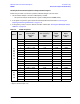
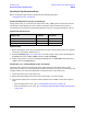
Equipment Type
Model or
Part Number
Alternate Model or
Part Number
Spectrum analyzer 8565E None
Power meter E4418B/19B E4418A/19A
Power sensor, 3.5 mm 8485A None
RF cable, 3.5 mm (f) to 3.5 mm (f) 85131C Any