Service Guide N5230C Agilent Technologies 4-Port PNA-L Microwave Network Analyzers (300 kHz–13.5 GHz) (300 kHz–20 GHz) Part Number N5230-90025 Printed in USA January 15, 2014 Supersedes: October 1, 2013 Agilent Technologies, Inc.
Warranty Statement THE MATERIAL CONTAINED IN THIS DOCUMENT IS PROVIDED “AS IS,” AND IS SUBJECT TO BEING CHANGED, WITHOUT NOTICE, IN FUTURE EDITIONS. FURTHER, TO THE MAXIMUM EXTENT PERMITTED BY APPLICABLE LAW, AGILENT DISCLAIMS ALL WARRANTIES, EITHER EXPRESS OR IMPLIED WITH REGARD TO THIS MANUAL AND ANY INFORMATION CONTAINED HEREIN, INCLUDING BUT NOT LIMITED TO THE IMPLIED WARRANTIES OF MERCHANTABILITY AND FITNESS FOR A PARTICULAR PURPOSE.
Assistance Product maintenance agreements and other customer assistance agreements are available for Agilent Technologies, Inc. products. For information about these agreements and for other assistance, contact Agilent. Refer to “Contacting Agilent” on page 2-11. Safety and Regulatory Information The safety and regulatory information pertaining to this product is located in Chapter 1, “Safety and Regulatory Information.” Safety Notes The following safety notes are used throughout this manual.
The Installation and Quick Start Guide helps you to quickly familiarize yourself with the analyzer. Procedures are provided for installing, configuring, and verifying the operation of the analyzer. Printing Copies of Documentation from the Web To print copies of documentation from the Web, download the PDF file from the Agilent web site: • Go to www.agilent.com. • Enter the product model number in the search function and click Search. • Click on the Manuals hyperlink.
Contents 1 Safety and Regulatory Information Information in This Chapter . . . . . . . . . . . . . . . . . . . . . . . . . . . . . . . . . . . . . . . . . . . . . . . . . . . . . . . . . . . . . . . . . . . . . . . 1-2 Chapter One at-a-Glance . . . . . . . . . . . . . . . . . . . . . . . . . . . . . . . . . . . . . . . . . . . . . . . . . . . . . . . . . . . . . . . . . . . . . . . 1-2 Safety Symbols . . . . . . . . . . . . . . . . . . . . . . . . . . . . . . . . . . . . . . . . . . . . . . . . . . . . .
Contents Review the Principles of Connector Care. . . . . . . . . . . . . . . . . . . . . . . . . . . . . . . . . . . . . . . . . . . . . . . . . . . . . . . . . . 3-5 About System Verification and Performance Tests . . . . . . . . . . . . . . . . . . . . . . . . . . . . . . . . . . . . . . . . . . . . . . . . . . . 3-6 System Specifications. . . . . . . . . . . . . . . . . . . . . . . . . . . . . . . . . . . . . . . . . . . . . . . . . . . . . . . . . . . . . . . . . . . . . . . . . .
Contents Rear Panel Troubleshooting . . . . . . . . . . . . . . . . . . . . . . . . . . . . . . . . . . . . . . . . . . . . . . . . . . . . . . . . . . . . . . . . . . . . . . 4-17 Checking the USB Ports . . . . . . . . . . . . . . . . . . . . . . . . . . . . . . . . . . . . . . . . . . . . . . . . . . . . . . . . . . . . . . . . . . . . . . . 4-17 Checking the SERIAL (RS-232), PARALLEL (1284-C), or VGA Port . . . . . . . . . . . . . . . . . . . . . . . . . . . . . . . . . . . 4-18 Checking the GPIB Port .
Contents 6 Replaceable Parts Information in This Chapter . . . . . . . . . . . . . . . . . . . . . . . . . . . . . . . . . . . . . . . . . . . . . . . . . . . . . . . . . . . . . . . . . . . . . . . 6-2 Chapter Six at-a-Glance . . . . . . . . . . . . . . . . . . . . . . . . . . . . . . . . . . . . . . . . . . . . . . . . . . . . . . . . . . . . . . . . . . . . . . . . 6-2 Ordering Information . . . . . . . . . . . . . . . . . . . . . . . . . . . . . . . . . . . . . . . . . . . . . . . . . . . . . . . . .
Contents Removing and Replacing the A21, A22, A23, and A24 Test Port Couplers and Coupler Mounting Blocks . . . . 7-38 Removing and Replacing the A25 60-dB Source Step Attenuator . . . . . . . . . . . . . . . . . . . . . . . . . . . . . . . . . . . . . . 7-40 Removing and Replacing the A26 60-dB Source Step Attenuator . . . . . . . . . . . . . . . . . . . . . . . . . . . . . . . . . . . . . . 7-42 Removing and Replacing the A29 Reference Switch, Limiter, and DC Block. . . . . . . . . . . . . . . . . . . .
Contents Contents-6 Service Guide N5230-90025
1 Safety and Regulatory Information Service Guide N5230-90025 1-1
Safety and Regulatory Information Information in This Chapter PNA Series Microwave Network Analyzers N5230C Information in This Chapter This chapter provides safety information that will help protect you and your network analyzer. It also contains information that is required by various government regulatory agencies. Chapter One at-a-Glance Section Title Summary of Content Start Page Safety Symbols Descriptions of CAUTION and WARNING symbols used throughout this manual.
PNA Series Microwave Network Analyzers N5230C Safety and Regulatory Information Safety Symbols Safety Symbols The following safety symbols are used throughout this manual. Familiarize yourself with each of the symbols and its meaning before operating this instrument. CAUTION Caution denotes a hazard. It calls attention to a procedure that, if not correctly performed or adhered to, could result in damage to or destruction of the instrument.
Safety and Regulatory Information General Safety Considerations PNA Series Microwave Network Analyzers N5230C 61010-1:2001 and 664 respectively. CAUTION Ventilation Requirements: When installing the product in a cabinet, the convection into and out of the product must not be restricted. The ambient temperature (outside the cabinet) must be less than the maximum operating temperature of the instrument by 4 C for every 100 watts dissipated in the cabinet.
PNA Series Microwave Network Analyzers N5230C Safety and Regulatory Information General Safety Considerations WARNING For continued protection against fire hazard, replace line fuse only with same type and rating. The use of other fuses or material is prohibited. WARNING The detachable power cord is the instrument disconnecting device. It disconnects the mains circuits from the mains supply before other parts of the instrument.
Safety and Regulatory Information Electrostatic Discharge Protection PNA Series Microwave Network Analyzers N5230C Electrostatic Discharge Protection Protection against electrostatic discharge (ESD) is essential while removing assemblies from or connecting cables to the network analyzer. Static electricity can build up on your body and can easily damage sensitive internal circuit elements when discharged. Static discharges too small to be felt can cause permanent damage.
PNA Series Microwave Network Analyzers N5230C Safety and Regulatory Information Regulatory Information Regulatory Information This section contains information that is required by various government regulatory agencies.
Safety and Regulatory Information Regulatory Information PNA Series Microwave Network Analyzers N5230C Instrument Markings The instruction documentation symbol. The product is marked with this symbol when it is necessary for the user to refer to the instructions in the documentation. The CE mark is a registered trademark of the European Community. (If accompanied by a year, it is when the design was proven.) The CSA mark is a registered trademark of the Canadian Standards Association.
PNA Series Microwave Network Analyzers N5230C KCC-REM-ATiXXXXXXXXXXX Safety and Regulatory Information Regulatory Information Korean Certification (KC) mark. Must include the marking’s identifier code (Agilent product specific) as follows: KCC-REM-ATi- WNANALYZERF01 Lithium Battery Disposal If the battery on the A15 CPU board assembly needs to be disposed of, dispose of it in accordance with your country’s requirements. If required, you may return the battery to Agilent Technologies for disposal.
Safety and Regulatory Information Regulatory Information 1-10 PNA Series Microwave Network Analyzers N5230C Service Guide N5230-90025
2 General Product Information Service Guide N5230-90025 2-1
General Product Information Information in This Chapter PNA Series Microwave Network Analyzers N5230C Information in This Chapter Chapter Two at-a-Glance Section Title Summary of Content Start Page Maintenance Cleaning instructions for the external surfaces of your analyzer. Page 2-3 Information about electrical maintenance of your analyzer. Analyzer Options Available A list of the options available for the microwave network analyzers.
PNA Series Microwave Network Analyzers N5230C General Product Information Maintenance Maintenance WARNING To prevent electrical shock, disconnect the analyzer from the mains source before cleaning. Use a dry cloth or one slightly dampened with water to clean the external case parts. Do not attempt to clean internally. Physical Maintenance Clean the cabinet, including the front panel, using a dry or slightly damp cloth only.
General Product Information Analyzer Options Available PNA Series Microwave Network Analyzers N5230C Option 010, Time Domain This option can be added to any other option combination. An Option 010 analyzer can display the time domain response of a network or test device by calculating the inverse Fourier transform of the frequency domain response. This calculation allows the Option 010 analyzer to show the response of a test device as a function of time or distance.
PNA Series Microwave Network Analyzers N5230C General Product Information Analyzer Options Available Option 1E1, Source Attenuator (Extended Power Range) This option is included in Options 145, 146, 245, and 246. This option adds a single 60-dB step attenuator in the signal path of the measurement ports. This step attenuator is used to adjust the power level (in 10 db steps) to the device under test (DUT) without changing the power in the reference path.
General Product Information Analyzer Accessories and Upgrades Available PNA Series Microwave Network Analyzers N5230C Analyzer Accessories and Upgrades Available To see a list of the accessories and upgrades available for the network analyzers, including ordering information, refer to the Agilent PNA Family Microwave Network Analyzers Configuration Guide, available online at http://cp.literature.agilent.com/litweb/pdf/5990-7745EN.
PNA Series Microwave Network Analyzers N5230C General Product Information Required Service Test Equipment Required Service Test Equipment Equipment Critical Specifications Recommended Model or Part Number Alternate Model or Part Number Usea Test Instruments and Software Frequency counter Freq: 10 MHz to 10.5 GHz Accuracy : 0.5 ppm 53151A Opt 001 None P, A, T Spectrum analyzer Min Freq: 1 MHz Max Freq: > 4 GHz Resolution BW: 300 Hz 8565E 856xE A, T Power meter Accuracy: ±0.
General Product Information Required Service Test Equipment PNA Series Microwave Network Analyzers N5230C Required Service Test Equipment (Cont’d) Equipment a Recommended Model or Part Number Critical Specifications Alternate Model or Part Number Useb Calibration and Verification Kits 3.5 mm calibration kit -- 3.5 mm verification kit -- 85052B DC to 26.5 GHz 85053B 300 kHz to 26.5 GHz 85052D DC to 26.5 GHz P,T None V A Cables BNC cable (2 required) 50, length 60 cm 8120-1839 None 3.
PNA Series Microwave Network Analyzers N5230C General Product Information Required Service Test Equipment Required Service Test Equipment (Cont’d) Equipmenta Critical Specifications Recommended Model or Part Number Alternate Model Number Useb Tools Extender board N/A E8356-60021 None T T-8 TORX driver 0.6 N-m (5 in-lb) setting N/A N/A R T-10 TORX driver 0.5, 0.8, and 1.0 N-m (4, 7, and 9 in-lb) settings N/A N/A T, R T-15 TORX driver 1.
General Product Information Agilent Support, Services, and Assistance PNA Series Microwave Network Analyzers N5230C Agilent Support, Services, and Assistance Information on the following topics is included in this section. • “Service and Support Options” • “Contacting Agilent” • “Shipping Your Analyzer to Agilent for Service or Repair” Service and Support Options The analyzer’s standard warranty period is one-year from the time of initial delivery.
PNA Series Microwave Network Analyzers N5230C General Product Information Agilent Support, Services, and Assistance Contacting Agilent Assistance with test and measurements needs and information on finding a local Agilent office are available on the Web at: http://www.agilent.com/find/assist If you do not have access to the Internet, please contact your Agilent field engineer. NOTE In any correspondence or telephone conversation, refer to the Agilent product by its model number and full serial number.
General Product Information Agilent Support, Services, and Assistance 2-12 PNA Series Microwave Network Analyzers N5230C Service Guide N5230-90025
3 Tests and Adjustments Service Guide N5230-90025 3-1
Tests and Adjustments Information in This Chapter PNA Series Microwave Network Analyzers N5230C Information in This Chapter This chapter contains procedures to help you check, verify, and adjust your PNA. • The checks verify the operation of the assemblies in your analyzer. • The verification compares the operation of your analyzer to a gold standard. • The adjustments allow you to tune your analyzer for maximum response.
PNA Series Microwave Network Analyzers N5230C Section Title Performance Tests (Agilent N7840A Software Package)a Summary of Content Start Page A brief summary of each performance test in the Agilent N7840A software package: Page 3-28 • Source Power Accuracy Test • Source Maximum Power Output Test • Source Power Linearity Test • Frequency Accuracy Test • Trace Noise Test • Receiver Compression Test • Noise Floor Test • Calibration Coefficients Test • Dynamic Accuracy Test Setups and
Tests and Adjustments Before You Begin PNA Series Microwave Network Analyzers N5230C Before You Begin Before checking, verifying, or adjusting the analyzer, refer to the following paragraphs to: • make sure the operating environment is within its requirements • make sure that proper electrostatic discharge (ESD) protection is provided • make sure the analyzer has warmed up properly to achieve system stability • review the principles of connector care Verify the Operating Environment Due to their o
PNA Series Microwave Network Analyzers N5230C Tests and Adjustments Before You Begin Review the Principles of Connector Care Proper connector care and connection techniques are critical for accurate and repeatable measurements. Refer to Table 3-1 for tips on connector care. Prior to making connections to your analyzer, carefully review the information about inspecting, cleaning, and gaging connectors. Refer to the calibration kit documentation for detailed connector care information.
Tests and Adjustments About System Verification and Performance Tests PNA Series Microwave Network Analyzers N5230C About System Verification and Performance Tests The performance of the network analyzer is specified in two ways: system specifications, and instrument specifications. It is the end user’s responsibility to determine which set of specifications is applicable to their use of the PNA.
PNA Series Microwave Network Analyzers N5230C Tests and Adjustments About System Verification and Performance Tests against the system specifications. If confirmation is successful, the measurement system is capable of making measurements to the accuracy specified by the graphs of measurement uncertainty.
Tests and Adjustments ANSI/NCSL Z540–1–1994 Verification PNA Series Microwave Network Analyzers N5230C ANSI/NCSL Z540–1–1994 Verification To meet the criteria for ANSI/NCSL Z540-1-1994, perform the preliminary checks and all performance tests without stopping to repair or adjust1. Refer to Figure 3-1 for test flow. Print data at the completion of all the tests, even if you are aware that the analyzer did not pass.
PNA Series Microwave Network Analyzers N5230C Tests and Adjustments Non-ANSI/NCSL Z540–1–1994 Verification Non-ANSI/NCSL Z540–1–1994 Verification For non-ANSI/NCSL Z540-1-1994, perform the preliminary checks and performance tests while stopping to troubleshoot. Refer to Figure 3-2 for test flow. Troubleshoot and repair the first problem encountered without continuing to other tests. After you troubleshoot, repair, and adjust, repeat the last failed portion and generate a new set of data.
Tests and Adjustments Preliminary Checks PNA Series Microwave Network Analyzers N5230C Preliminary Checks Preliminary checks include the following: • “The Operator’s Check” on page 3-10 The operator’s check tests the network analyzer’s basic functionality of the source, switch, and receivers. • “The Test Port Cable Checks” on page 3-12 The test port cable checks are not required, but are recommended to verify the performance of the test port cables before performing the verification test.
PNA Series Microwave Network Analyzers N5230C Tests and Adjustments Preliminary Checks The PNA Operator’s Check dialog box will look different for different PNA model numbers and installed options. Some of the tests are performed only if the appropriate options are installed in the PNA. Figure 3-3 Operator’s Check Dialog Box If the Operator’s Check Fails 1. Clean the test ports, shorts, and adapters. Torque connections to specification. Repeat the check. 2.
Tests and Adjustments Preliminary Checks PNA Series Microwave Network Analyzers N5230C The Test Port Cable Checks A faulty test port cable can cause a failure in the verification test. The following checks are not required, but are recommended to verify the performance of the test port cable.
PNA Series Microwave Network Analyzers N5230C Tests and Adjustments Preliminary Checks Cable Return Loss Check 1. Press Preset. 2. Perform a one-port calibration on Port 1, 1-Port Reflection. Refer to the embedded help in the analyzer if necessary. 3. Connect the test port cable to Port 1. Connect a broadband load to the other end of the cable. Tighten to the specified torque for the connector type. The analyzer now displays the return loss of the cable. 4. From the Marker menu, click Marker Search.
Tests and Adjustments Preliminary Checks PNA Series Microwave Network Analyzers N5230C Cable Insertion Loss Check 1. With the test port cable still connected to Port 1, connect a short to the other end of the cable. 2. From the Marker menu, click Marker Search. In the Marker Search dialog box, in the Search Type box, select Minimum. Click Execute, and then click OK. 3. The displayed response is twice the actual loss.
PNA Series Microwave Network Analyzers N5230C Tests and Adjustments Preliminary Checks Cable Magnitude and Phase Stability Check 1. With the test port cable still connected to Port 1, connect a short to the other end of the cable. 2. Press Preset. 3. On the Trace menu, click New Trace. In the New Trace dialog box, click the S11 box, and then click OK. 4. On the Trace menu, click Format. In the Format dialog box, click Phase, and then click OK. 5. On the Channel menu, click Average.
Tests and Adjustments Preliminary Checks Figure 3-6 PNA Series Microwave Network Analyzers N5230C Typical Cable Magnitude and Phase Stability Response If the Cable Magnitude and Phase Stability Check Fails 1. Clean the cable and devices and torque to specification. Repeat the check. 2. If the check still fails, the cable should be repaired or replaced.
PNA Series Microwave Network Analyzers N5230C Tests and Adjustments Preliminary Checks Cable Connector Repeatability Check NOTE The connector repeatability measurement should be done at the test port as well as at the end of the test port cable. 1. With the test port cable still connected to Port 1, connect a broadband load to the other end of the cable. 2. Press Preset. 3. On the Channel menu, click Average. In the Average dialog box, click the Average ON check box.
Tests and Adjustments Preliminary Checks Figure 3-7 PNA Series Microwave Network Analyzers N5230C Typical Cable Connector Repeatability Response If the Cable Connector Repeatability Check Fails 1. Clean the cable and devices, and torque to specification. Repeat the check. 2. If the check still fails, the cable should be repaired or replaced.
PNA Series Microwave Network Analyzers N5230C Tests and Adjustments System Verification System Verification System verification is used to verify system-level, error-corrected uncertainty limits for network analyzer measurements. The verification procedure is automated and is contained in the firmware of the analyzer. The device data provided with the verification kit has a traceable path to a national standard.
Tests and Adjustments System Verification PNA Series Microwave Network Analyzers N5230C Measurement Uncertainty Measurement uncertainty is defined as the sum of: • the residual systematic (repeatable) errors, and • the random (non-repeatable) errors in the measurement system after calibration. The systematic errors are: • directivity, • source match, • load match, • reflection and transmission frequency tracking, and • isolation (crosstalk).
PNA Series Microwave Network Analyzers N5230C Tests and Adjustments System Verification Measurement Traceability To establish a measurement traceability path to a national standard for a network analyzer system, the overall system performance is verified through the measurement of devices that have a traceable path. This is accomplished by measuring the devices in an Agilent verification kit.
Tests and Adjustments System Verification PNA Series Microwave Network Analyzers N5230C Performing System Verification The following verification procedure is automated by the analyzer firmware.
PNA Series Microwave Network Analyzers N5230C Tests and Adjustments System Verification Cable Substitution The test port cables specified for the network analyzer system have been characterized for connector repeatability, magnitude and phase stability with flexing, return loss, insertion loss, and aging rate. Since test port cable performance is a significant contributor to the system performance, cables of lower performance will increase the uncertainty of your measurement.
Tests and Adjustments System Verification PNA Series Microwave Network Analyzers N5230C Verification Kit box. Refer to Figure 3-9. 5. Under Printer Output, click one of the following options. Refer to Figure 3-9. • Print Tabular Data: Prints the verification data in tabular form which includes measured data and uncertainty limits. For an example, refer to Figure 3-11 on page 3-26. • Print Graphs: Prints the verification data in graphical form.
PNA Series Microwave Network Analyzers N5230C Tests and Adjustments System Verification If the System Fails the Verification Test IMPORTANT Inspect all connections. Do not remove the cable from the analyzer test port. This will invalidate the calibration that you performed earlier. 1. Disconnect and clean the device that failed the verification test. 2. Reconnect the device making sure that all connections are torqued to the proper specifications. 3. Measure the device again. 4.
Tests and Adjustments System Verification PNA Series Microwave Network Analyzers N5230C Interpreting the Verification Results Figure 3-11 shows an example of typical verification results with Print Tabular Data selected in the Printer Output area of the System Verification dialog box. At the top of the printed output is the name of the device, the serial number of the device, and the date tested.
PNA Series Microwave Network Analyzers N5230C Tests and Adjustments System Verification Figure 3-12 shows an example of typical verification results with Print Graphs selected in the Printer Output area of the System Verification dialog box. The printed graphical results show the following: • the name of the device measured • the serial number of the device • the parameters measured • Results of the measurements. Labeled as A in Figure 3-12.
Tests and Adjustments Performance Tests (Agilent N7840A Software Package) PNA Series Microwave Network Analyzers N5230C Performance Tests (Agilent N7840A Software Package) The Agilent N7840A software package verifies the electrical performance of your N5230C microwave PNA. The software automatically configures your analyzer to execute the performance tests. The N7840A software package is not included with the analyzer; it must be ordered separately.
PNA Series Microwave Network Analyzers N5230C Tests and Adjustments Performance Tests (Agilent N7840A Software Package) Source Maximum Power Output Test Function of the Test: To confirm the maximum source output power of your network analyzer over its full frequency range. Specification Tested: Test Port Output–Maximum Leveled Power Equipment Used: A power meter, power sensors, and adapters. Description of the Test: 1. A power sensor is connected to Port 1. 2.
Tests and Adjustments Performance Tests (Agilent N7840A Software Package) PNA Series Microwave Network Analyzers N5230C Frequency Accuracy Test Function of the Test: To verify the frequency accuracy and range of the analyzer’s source output. Specification Tested: Test Port Output–CW Accuracy Equipment Used: A frequency counter, a test cable, and adapters. Description of the Test: 1. Port 1 is connected to a frequency counter. 2. A series of frequencies across the band are checked.
PNA Series Microwave Network Analyzers N5230C Tests and Adjustments Performance Tests (Agilent N7840A Software Package) Receiver Compression Test Function of the Test: To measure the compression at the analyzer’s specified maximum power level for the receivers. Specification Tested: Test Port Input–Maximum Test Port Input Level Equipment Used: The compression test set, a power meter, power sensors, two test cables, and a calibration kit.
Tests and Adjustments Performance Tests (Agilent N7840A Software Package) PNA Series Microwave Network Analyzers N5230C Noise Floor Test Function of the Test: To measure the absolute power level of the noise floor for the analyzer’s receivers. Specification Tested: Test Port Input–Test Port Noise Floor Equipment Used: A power meter, power sensor, a calibration kit, and a test cable. Description of the Test: 1.
PNA Series Microwave Network Analyzers N5230C Tests and Adjustments Performance Tests (Agilent N7840A Software Package) Calibration Coefficients Test Function of the Test: To verify the uncorrected calibration coefficients of your analyzer. The calibration coefficients are measured in forward and reverse direction. Refer to “Error Terms” in Chapter 8 for error term information relating to the calibration coefficients measured.
Tests and Adjustments Performance Tests (Agilent N7840A Software Package) PNA Series Microwave Network Analyzers N5230C Dynamic Accuracy Test Function of the Test: To measure the relative power linearity of the analyzer’s receivers. Specification Tested: Test Port Input–Dynamic Accuracy Equipment Used: The dynamic accuracy test set, a power meter (E4418B or E4419B), power sensors, and two test cables. Description of the Test: 1.
PNA Series Microwave Network Analyzers N5230C Tests and Adjustments Adjustments Adjustments These adjustments are firmware-driven tests that are used to fine-tune your analyzer. If multiple adjustments are to be performed, perform them in the order listed.
Tests and Adjustments Adjustments PNA Series Microwave Network Analyzers N5230C 4. Click Begin Adj, and then follow the instructions as they are displayed. EE Default Adjustment This sets the EEPROM data to their default values. Procedure 1. Press UTILITY System , then Service , then Adjustments , then click EE Default Adjustment. 2. On the dialog box, select the appropriate adjustment (Ex: Source Synth) for the replaced assembly. 3.
PNA Series Microwave Network Analyzers N5230C Tests and Adjustments Adjustments Source Calibration Adjustment The source calibration is used to adjust your network analyzer for a flat source power across its full frequency range. There are differences between each test port; therefore, an adjustment is required for each port. Equipment Used for the Source Calibration Adjustment Equipment Type Model or Part Number Alternate Model or Part Number Power meter E4418B/E4419B E4418A/E4419A Power sensor, 3.
Tests and Adjustments Adjustments PNA Series Microwave Network Analyzers N5230C Receiver Calibration Adjustment The receiver calibration is used to adjust the network analyzer receivers for a flat response across its full frequency range: 1. A power meter/sensor is connected to Port 1, as shown in Figure 3-15, to establish a reference for flatness. 2. A cable is inserted between the power sensor and the test port, as shown in Figure 3-16, to establish a reference for the cable. 3.
PNA Series Microwave Network Analyzers N5230C Figure 3-15 Tests and Adjustments Adjustments Setup 1 for the Receiver Calibration Adjustment 2. On the System menu, point to Service, Adjustments, and then click Receiver Calibration. 3. Ensure the GPIB settings are correct. 4. Click Calibrate, and then follow the instructions as they are displayed.
Tests and Adjustments Adjustments Figure 3-17 3-40 PNA Series Microwave Network Analyzers N5230C Setup 3 for the Receiver Calibration Adjustment Service Guide N5230-90025
4 Troubleshooting Service Guide N5230-90025 4-1
Troubleshooting Information in This Chapter PNA Series Microwave Network Analyzers N5230C Information in This Chapter The information in this chapter helps you: • Identify the portion of the analyzer at fault. • Locate the specific troubleshooting procedure to identify the assembly or peripheral at fault. The sections in this chapter are arranged in a logical troubleshooting order. The following table lists the sections and a brief summary of what to look for in that section.
PNA Series Microwave Network Analyzers N5230C Troubleshooting Protect Against Electrostatic Discharge (ESD) Protect Against Electrostatic Discharge (ESD) This is important. If not properly protected against, electrostatic discharge can seriously damage your analyzer, resulting in costly repair. CAUTION To reduce the chance of electrostatic discharge, follow all of the recommendations outlined in “Electrostatic Discharge Protection” on page 1-6, for all of the procedures in this chapter.
Troubleshooting Getting Started with Troubleshooting PNA Series Microwave Network Analyzers N5230C Getting Started with Troubleshooting Where you begin troubleshooting depends upon the symptoms of the failure. Start by checking the basics as outlined in the following section. Also review the flowchart in Figure 4-1 on page 4-5. You should then be able to determine where in the troubleshooting procedure to begin, to locate the failed assembly.
PNA Series Microwave Network Analyzers N5230C Troubleshooting Getting Started with Troubleshooting Troubleshooting Organization Follow the flowgraph in Figure 4-1 to help direct you to the correct section for troubleshooting the analyzer. Figure 4-1 Troubleshooting Organization Flowchart Go to “Power Up Troubleshooting” on page 4-6. Go to “Front Panel Troubleshooting” on page 4-12. Go to “Rear Panel Troubleshooting” on page 4-17. Go to “Measurement System Troubleshooting” on page 4-23.
Troubleshooting Power Up Troubleshooting PNA Series Microwave Network Analyzers N5230C Power Up Troubleshooting WARNING Immediately unplug the instrument from the ac power line if the unit shows any of the following symptoms: • Smoke, arcing, or unusual noise from inside the analyzer. • A circuit breaker or fuse on the main ac power line opens. Check your network analyzer for evidence that it is powering up correctly.
PNA Series Microwave Network Analyzers N5230C Troubleshooting Power Up Troubleshooting Power Supply Check NOTE There are no fuses to replace within the power supply. If you determine that the power supply is the failed assembly, replace the power supply. A catastrophic failure in the power supply can be determined by observing the line switch: 1. Ensure that the instrument is plugged in with the power switch in the standby position (power not switched on). Verify that the line switch glows yellow.
Troubleshooting Power Up Troubleshooting PNA Series Microwave Network Analyzers N5230C Measure the Individual Voltage Supplies WARNING The instrument contains potentially hazardous voltages. Refer to the safety symbols provided on the instrument and in “General Safety Considerations” on page 1-3 before operating the unit with the cover removed. Make sure that the safety instructions are strictly followed. Failure to do so can result in personal injury or loss of life.
PNA Series Microwave Network Analyzers N5230C Table 4-1 Troubleshooting Power Up Troubleshooting Extender Board Measurement Points Measurement Location Signal Description Test Equipment Useda Expected Level (Vdc) Approximate Resistance (W) A +5V power supply DMM +5.0 285 B -15V power supply DMM 15.0 12.7 k C -5V power supply DMM 5.0 7.2 k D +9V power supply DMM +9.0 4.0 k E +15V power supply DMM +15.0 3.0 k F +15V power supply DMM +15.0 2.
Troubleshooting Power Up Troubleshooting PNA Series Microwave Network Analyzers N5230C Boards” on page 7-16). 6. Remove the A8 multiplier board (refer to “Removing and Replacing the A5 through A10 Boards” on page 7-16). 7. Remove the A9 fractional-N synthesizer board (refer to “Removing and Replacing the A5 through A10 Boards” on page 7-16) 8. Remove the A10 frequency reference board (refer to “Removing and Replacing the A5 through A10 Boards” on page 7-16). 9.
PNA Series Microwave Network Analyzers N5230C Troubleshooting Power Up Troubleshooting If the Fans Are Not Operating CAUTION The power supply may be in thermal shutdown if the instrument has been operating without the fans running. Allow the instrument to cool down before troubleshooting. If all three fans are not operating, suspect a power supply problem or a defective A14 system motherboard. Refer to “Power Supply Check” on page 4-7 to check the individual supplies.
Troubleshooting Front Panel Troubleshooting PNA Series Microwave Network Analyzers N5230C Front Panel Troubleshooting The front panel assembly consists of the A1 keypad, the A2 display assembly, the A3 front panel interface board, the touchscreen and touchscreen controller board, the inverter board, and the USB board. The following tests verify the operation of the front panel assembly when the analyzer is in the measurement mode.
PNA Series Microwave Network Analyzers N5230C Troubleshooting Front Panel Troubleshooting Front Panel Keypad and RPG Test Test the front panel keypad by running the front panel test. To run the front panel test, perform the following: Press UTILITY System , then Service , then More , then Front Panel Test . A Front Panel Key Test Utility dialog box will be displayed, as shown in Figure 4-4.
Troubleshooting Front Panel Troubleshooting PNA Series Microwave Network Analyzers N5230C Checking the Front Panel Keys To check the front panel keys, push each key and compare the name in the Key Label box to the name physically labeled on the key cap. These names are also in Table 4-2 below. • If all the key names are correct, then the front panel keypad is working. If some of the keys are not working, suspect a faulty keypad.
PNA Series Microwave Network Analyzers N5230C Troubleshooting Front Panel Troubleshooting Checking the RPG (Front Panel Knob) To check the RPG knob: 1. Press the UTILITY Preset key. 2. Rotate the knob and check for a fluid movement of numbers on the analyzer display. • If the movement of numbers is not smooth or no numbers appear at all, suspect a faulty A3 front panel interface board. To replace the A3 front panel interface board, refer to “Replacing the A3 Front Panel Interface Board” on page 7-12.
Troubleshooting Front Panel Troubleshooting PNA Series Microwave Network Analyzers N5230C Checking the USB Board To verify proper operation of the USB board: • Connect a known good USB device, such as a USB mouse, to a front panel USB port. • Wait 15 seconds for the analyzer to verify the device connection, and then check the operation of the USB device. • If the device performs correctly, the USB board is functioning properly. • If the device does not perform correctly, the USB board is faulty.
PNA Series Microwave Network Analyzers N5230C Troubleshooting Rear Panel Troubleshooting Rear Panel Troubleshooting Each rear panel connector is associated with a hardware group in the analyzer. You can use the data at these rear panel connectors to help troubleshoot these hardware groups in addition to testing the connectors.
Troubleshooting Rear Panel Troubleshooting PNA Series Microwave Network Analyzers N5230C Checking the SERIAL (RS-232), PARALLEL (1284-C), or VGA Port To verify the proper operation of the SERIAL, PARALLEL, or VGA port: • Connect a known good serial, parallel, or VGA peripheral device. • Wait 15 seconds for the analyzer to verify the device connection, and then check the operation of the peripheral device. • If the peripheral device performs correctly, the port is functioning properly.
PNA Series Microwave Network Analyzers N5230C Troubleshooting Rear Panel Troubleshooting Troubleshooting Systems with Controllers Passing the preceding test indicates that the analyzer's peripheral functions are operating normally. Therefore, if the analyzer has not been operating properly with an external controller, check the following: • The GPIB interface hardware is incorrectly installed or not operational. (Refer to the embedded help in your analyzer.) • The programming syntax is incorrect.
Troubleshooting Rear Panel Troubleshooting PNA Series Microwave Network Analyzers N5230C for the results of a successful ping. 5. The analyzer attempts four cycles of communications with the indicated LAN device. • It displays the time it took to complete each cycle. • Each cycle times-out after one second if no communication is established and the message, Request timed out, is displayed. • It is common for the first of the four cycles to time-out even though subsequent cycles pass.
PNA Series Microwave Network Analyzers N5230C Troubleshooting Rear Panel Troubleshooting Testing Between Two Analyzers The ability of the analyzer's LAN to function can be easily tested by connecting two analyzers together using a “crossover cable” (a short length of cable with an RJ-45 connector on each end). Some network hubs have the capability to make a crossover connection using two normal, or straight-through, cables.
Troubleshooting Rear Panel Troubleshooting Table 4-3 PNA Series Microwave Network Analyzers N5230C LAN Pin Definitions and Wire Color Codes Pin Number Color Pin Number Color 1 (transmit +) White/orange 5 White/blue 2 (transmit ) Orange 6 (receive ) Green 3 (receive +) White/green 7 White/brown 4 Blue 8 Brown 2. Cut the wires going to pins 1, 2, 3, and 6. Strip away a small amount of insulation from each of the eight cut ends. a.
PNA Series Microwave Network Analyzers N5230C Troubleshooting Measurement System Troubleshooting Measurement System Troubleshooting This section provides troubleshooting procedures for the measurement portion of the PNA. In this section, the analyzer is used as a tool to help isolate the suspected faulty functional group. Once the faulty functional group is determined, troubleshooting steps are provided to help you isolate the faulty assembly or part.
Troubleshooting Measurement System Troubleshooting PNA Series Microwave Network Analyzers N5230C EEPROM Headers The network analyzer application uses the firmware revision information stored in the pc board header EEPROM. If the information stored in any EEPROM is incorrect, the network analyzer may not operate properly. The following table lists the pc boards in your network analyzer that contain EEPROM headers.
PNA Series Microwave Network Analyzers N5230C Troubleshooting Measurement System Troubleshooting Error Messages SOURCE UNLEVELED: The source ALC circuit on the A16 test set motherboard is running open-loop. Check the cable connections for W31 and W32 between the A19 MASSQuad and the A16 test set motherboard. UNLEVELED, SOURCE 1: (Options 146 and 246) The source ALC circuit on the A16 test set motherboard is running open-loop.
Troubleshooting Measurement System Troubleshooting PNA Series Microwave Network Analyzers N5230C Verifying the A, B, C, D, and R Traces (Standard S-Parameter Mode) NOTE There is no way to view the frequency offset receiver response (Option 080). However, some standard S-parameter receiver trace information is helpful in troubleshooting the frequency offset section of the PNA. It is therefore recommended that you run this test even if you only suspect the frequency offset section of malfunctioning.
PNA Series Microwave Network Analyzers N5230C • For analyzers with Options 146 and 246, traces A, B, C, D, R1, and R3 are displayed in six separate data windows as shown in Figure 4-8. Identifying discrepancies of the traces in these windows can help you to isolate the faulty assembly.
Troubleshooting Measurement System Troubleshooting PNA Series Microwave Network Analyzers N5230C Where to Begin Troubleshooting For the purposes of troubleshooting, the analyzer block diagram is divided into the following functional groups: • the source group — — — — — — — • the signal separation group — — — — — — • A6, A8, and A12 (Options 146 and 246 only) multipliers A7, A9, and A13 (Options 146 and 246 only) fractional-N synthesizers A10 frequency reference A16 test set motherboard A17 QABC board
PNA Series Microwave Network Analyzers N5230C Troubleshooting Measurement System Troubleshooting All Traces • If all traces are missing in all bands, the problem is most likely in the source group. However, a missing or disabled DSP driver may exhibit the same or similar symptoms. To verify that this DSP driver is present and enabled: 1. Click My Computer, Properties, Hardware tab, Device Manager. Expand Agilent PNA DSP Device.
Troubleshooting Measurement System Troubleshooting PNA Series Microwave Network Analyzers N5230C Checking the Source Group Source Group Tests Equipment Used for These Tests Equipment Type Model or Part Number Alternate Model or Part Number Spectrum analyzer 8565E None Power meter E4418B/19B E4418A/19A Power sensor, 3.5 mm 8485A None RF cable, 3.5 mm (f) to 3.5 mm (f) 85131C Any Getting Ready to Test Before checking the assemblies, you must open the analyzer.
PNA Series Microwave Network Analyzers N5230C Troubleshooting Measurement System Troubleshooting A phase lock problem is due to either: • faulty RF signal generation (caused by the A10, A9, A8, or A19 board or by the A13, A12, or A18 board for Options 146 and 246) • faulty LO signal generation (caused by the A10, A7 or A6 board) RF Signal Troubleshooting To isolate a broadband RF signal generation failure, check the test port output power: 1.
Troubleshooting Measurement System Troubleshooting PNA Series Microwave Network Analyzers N5230C 6. If the signal is present, reconnect cable W2, and then continue with “Checking the A7 Fractional-N Synthesizer Output, Band 4” on page 4-32. Checking the A7 Fractional-N Synthesizer Output, Band 4 Perform this procedure if you observe a problem in band 4 in all receivers. 1. Refer to the block diagram at the back of this chapter and to “Top Cables, All Options Except 146/246” on page 6-14.
PNA Series Microwave Network Analyzers N5230C Troubleshooting Measurement System Troubleshooting Checking the A7 Fractional-N Synthesizer Output, Bands 5 through 17 Perform this procedure if you observe a problem in bands 5 through 17 in all receivers. 1. Set the network analyzer to measure a CW frequency of 2 GHz. • The spectrum analyzer should measure a signal at 2 GHz (plus the 7.66 MHz offset). 2. If the signal is not present, replace the A7 fractional-N synthesizer board.
Troubleshooting Measurement System Troubleshooting PNA Series Microwave Network Analyzers N5230C Checking the A6 Multiplier Output, All Bands Perform this procedure if you observe a problem in all bands in all receivers. 1. Refer to the block diagram at the end of this chapter and to “Top Cables, All Options Except 146/246” on page 6-14. Locate the flexible cable W3, at the A6 multiplier board. 2. Disconnect W2 from the A6 board. 3. Connect the spectrum analyzer to the open connector. 4.
PNA Series Microwave Network Analyzers N5230C CAUTION Troubleshooting Measurement System Troubleshooting Be careful not to damage the center pins of the semirigid cable. Some flexing of the cables is necessary to measure the output. 2. Using a 5/16 inch torque wrench, disconnect W4 at A9J106. 3. Connect the spectrum analyzer to A9J106. 4. Set the network analyzer to a CW frequency of 1 GHz. • The spectrum analyzer should measure a signal at 1 GHz (plus the 7.66 MHz offset). 5.
Troubleshooting Measurement System Troubleshooting PNA Series Microwave Network Analyzers N5230C 1. Refer to the block diagram at the end of this chapter and to “Top Cables, Options 146/246 (Side View)” on page 6-20. Locate the flexible cable W62, at the A13 fractional-N synthesizer board. 2. Disconnect W62 from A13J101. 3. Connect the spectrum analyzer to A13J101. 4. Set the network analyzer for an S33 measurement at a CW frequency if 500 MHz and observe the spectrum analyzer measurement.
PNA Series Microwave Network Analyzers N5230C Troubleshooting Measurement System Troubleshooting Checking the A13 Fractional-N Synthesizer Output, Bands 5 through 17 (Options 146 and 246) Perform this procedure if you observe a problem in bands 5 through 17 in the C and D receivers. 1. Set the network analyzer for an S33 measurement at a CW frequency of 2 GHz. • The spectrum analyzer should measure a signal at 2 GHz (plus the 7.66 MHz offset). 2.
Troubleshooting Measurement System Troubleshooting PNA Series Microwave Network Analyzers N5230C Checking the Signal Separation Group Before checking the signal separation group, perform the following procedures: • “Getting Ready to Test” on page 4-30 Checking the Output Power of the A, B, C, and D Signals Using a power meter, you can measure the outputs of the A, B, C, and D signals from the front panel. The measurement results will help you isolate a faulty assembly.
PNA Series Microwave Network Analyzers N5230C Troubleshooting Measurement System Troubleshooting Checking the Signal through the Signal Separation Path For all of the following checks, refer to the block diagrams at the end of this chapter and to: • “Bottom Assemblies, Options 140 and 240” on page 6-22 • “Bottom Assemblies, Options 146 and 246” on page 6-30 Trace loss in the signal separation group is due to one or more of the following assemblies being defective: • A18 MASSQuad (Options 146 and 246
Troubleshooting Measurement System Troubleshooting • PNA Series Microwave Network Analyzers N5230C Analyzers with Options 145 and 245 — Port; W40 of A19 — Port 2; W41 of A19 — Port 3; W42 of A19 — Port 4; W43 of A19 • Analyzers with Options 146 and 246 — Port 1; W40 of A19 — Port 2; W41 of A19 — Port 3; W64 of A18 — Port 4; W65 of A18 2. Using a 5/16-inch torque wrench, disconnect the semirigid cable at the MASSQuad. 3. Connect the spectrum analyzer to the open connector.
PNA Series Microwave Network Analyzers N5230C Troubleshooting Measurement System Troubleshooting 2. Using a 5/16-inch torque wrench, disconnect the semirigid cable at the A19 MASSQuad. 3. Connect the spectrum analyzer to the A19 MASSQuad connector. Set the spectrum analyzer to measure a signal at 1 GHz. 4. If the 1 GHz signal is not present, replace the A19 MASSQuad. Refer to “Removing and Replacing the A19 MASS 26.5 (MASSQuad) and MASSQuad Mounting Block” on page 7-34. 5.
Troubleshooting Measurement System Troubleshooting PNA Series Microwave Network Analyzers N5230C Checking the Receiver Group Equipment Used for These Tests Equipment Type Model or Part Number Alternate Model or Part Number Spectrum analyzer 8565E 856xEa a. Must be capable of measuring a signal at 7.66 MHz. Getting Ready to Test Before checking the assemblies, you must open the analyzer.
PNA Series Microwave Network Analyzers N5230C Troubleshooting Measurement System Troubleshooting If the measured signal is not present on any of the channels and the analyzer is not equipped with Option 146 or 246, replace the A20 mixer brick. Refer to “Removing and Replacing the A20 Mixer Brick (QuintBrick)” on page 7-36. Checking the A29 Reference Channel Switch, Limiter, and DC Block (Options 146 and 246 Only) 1. Set the network analyzer for an S11 measurement with a CW frequency of 1 GHz. 2.
Troubleshooting Measurement System Troubleshooting 4-44 PNA Series Microwave Network Analyzers N5230C Service Guide N5230-90025
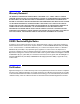
REAR PANEL INTERCONNECTS FRONT PANEL INTERCONNECTS N5230C PNA-L Overall Block Diagram 4-Port, 300 kHz to 13.5 GHz and 20 GHz Options 140 and 240 Service Guide: N5230-90024 A1 KEYPAD RPG INVERTER A2 DISPLAY DISPLAY CONTROL A3 FRONT PANEL INTERFACE VGA VGA INTERFACE PCI BUS PCI BUS W13 7.66 MHz * I W23 J4 W14 7.66 MHz* I C C 15 MHz VIDEO PROCESSOR R B W24 J5 ADC RAM VIDEO RAM D D 15 MHz A41 HARD DISK DRIVE 20.0 MHz W15 W16 5 MHz I J3 R D 20.0 MHz W12 7.
Troubleshooting Instrument Block Diagrams Sheet 1 4-46 PNA Series Microwave Network Analyzers N5230C Service Guide N5230-90025
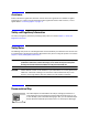
REAR PANEL INTERCONNECTS FRONT PANEL INTERCONNECTS N5230C PNA-L Overall Block Diagram 4-Port, 300 kHz to 13.5 GHz and 20 GHz Options 145 and 245 Service Guide: N5230-90024 A1 KEYPAD RPG INVERTER A2 DISPLAY DISPLAY CONTROL Port 1 W21 J1 ADC 20.0 MHz A A 15 MHz EEPROM PCI BUS MAIN CPU GPIB PORT INTERFACE PCI BUS B LAN 10/100 BASE-T ETHERNET VGA VGA INTERFACE RAM R A W60 CPLR ARM 20.0 MHz I C C Port 2 W54 7.
Troubleshooting Instrument Block Diagrams Sheet 2 4-48 PNA Series Microwave Network Analyzers N5230C Service Guide N5230-90025
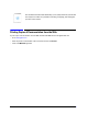
REAR PANEL INTERCONNECTS FRONT PANEL INTERCONNECTS N5230C PNA-L Overall Block Diagram 4-Port, 300 kHz to 13.5 GHz and 20 GHz Options 146 and 246 Service Guide: N5230-90024 A1 KEYPAD RPG A2 DISPLAY INVERTER DISPLAY CONTROL A3 FRONT PANEL INTERFACE VGA VGA INTERFACE PCI BUS I RCVR B IN 20.0 MHz ADC I C C 15 MHz VIDEO PROCESSOR VIDEO RAM B CPLR ARM W24 J5 ADC RAM Port 3 D 15 MHz A41 HARD DISK DRIVE D W55 I 5 MHz CPLR ARM J3 10 ƒ 10 MHz HIGH STAB OCXO J4 P.
Troubleshooting Instrument Block Diagrams Sheet 3 4-50 PNA Series Microwave Network Analyzers N5230C Service Guide N5230-90025
5 Theory of Operation Service Guide N5230-90025 5-1
Theory of Operation Information in This Chapter PNA Series Microwave Network Analyzers N5230C Information in This Chapter This chapter provides a general description of the operating theory of the N5230C 4-port PNA-L microwave network analyzer. • Theory of operation is explained to the assembly level only. • Component-level circuit theory is not provided. • Simplified block diagrams are included for each functional group.
PNA Series Microwave Network Analyzers N5230C Theory of Operation Network Analyzer System Operation Network Analyzer System Operation The PNA-L network analyzer generates a phase-locked incident signal and an LO signal from the internal synthesized source. By means of signal separation, the incident signal is divided into a reference signal and a test signal.
Theory of Operation Network Analyzer System Operation PNA Series Microwave Network Analyzers N5230C Synthesized Source Group The built-in synthesized source generates a swept, stepped, or continuous wave (CW) signal in the frequency ranges as listed in Table 5-1. The source group provides two signals: an LO signal and an incident signal. These two signals are normally at the same frequency (except for a 7.
PNA Series Microwave Network Analyzers N5230C Theory of Operation Network Analyzer System Operation Signal Separation Group The incident signal from the source group is separated into a reference path and a test path. The reference signal is transmitted to the receiver group. The test signal is transmitted through—and reflected from—the DUT and is then transmitted to the receiver group.
Theory of Operation Synthesized Source Group Operation PNA Series Microwave Network Analyzers N5230C Synthesized Source Group Operation The source group produces a stable output signal by phase locking a synthesized voltage-controlled oscillator (VCO). Refer to Table 5-2 on page 5-8 for the full frequency range of the source. The outputs at the front panel test ports are swept, stepped or CW signals. Maximum leveled output powers are listed in Table 5-1 on page 5-4.
PNA Series Microwave Network Analyzers N5230C Figure 5-2 Theory of Operation Synthesized Source Group Operation Source Group (One Source) Service Guide N5230-90025 5-7
Theory of Operation Synthesized Source Group Operation 240, 245, or 246 140, 145, 146, 240, 245, or 246 Options Table 5-2 PNA Series Microwave Network Analyzers N5230C Subsweep Frequencies Band A20 Mixer Brick L.O. Harmonic A7 Frac-N Synthesizer Frequency (GHz) A6 Multiplier Frequency (GHz) A9/A13 Frac-N Synthesizer Frequency (GHz) A8 Multiplier Frequency (GHz) A19/A18 MASSQuad Frequency (GHz) 0 1 0.008 to 0.009 0.008 to 0.009 .0003 to 0.001 .0003 to 0.001 .0003 to 0.001 1 1 0.
PNA Series Microwave Network Analyzers N5230C Theory of Operation Synthesized Source Group Operation Frequency Offset Operation (Option 080) Since the A7, A9 and A13 fractional-N synthesizer boards each contain their own phase lock circuitry, they can be phase locked independently to different output frequencies. Normally the LO signal is automatically tuned to a frequency 7.66 MHz higher than that of the test signal to create the 7.66 MHz difference frequency (IF) in the A20 mixer brick.
Theory of Operation Synthesized Source Group Operation PNA Series Microwave Network Analyzers N5230C A10 Frequency Reference Board This assembly provides stable reference frequencies to the rest of the instrument. A high stability 10 MHz oven-controlled crystal oscillator (OCXO) normally provides the frequency standard. However, if a 10 MHz external reference signal is detected at the 10 MHz EXT REF IN port on the rear panel, it is used as the frequency reference instead.
PNA Series Microwave Network Analyzers N5230C Theory of Operation Synthesized Source Group Operation A16 Test Set Motherboard The A16 test set motherboard serves these functions: • to act as an interface between the A15 CPU board and the auxiliary rear panel interconnects. • to provide ALC signals to the A19 MASSQuad. • to route control signals to the signal separation group. Refer to “Signal Separation Group Operation” on page 5-16 for more information.
Theory of Operation Synthesized Source Group Operation Table 5-3 PNA Series Microwave Network Analyzers N5230C TEST SET I/O Connector Pin Assignments DB-25 Female Connector Pin Numbers Name Function 1 SEL0 TTL out, test set select bit 0, tied to 0 V 2 Sweep Holdoff In TTL in, low level holds off sweep 3–6 AD12–AD8 TTL I/O, address and latched data 7 GND 0 V, ground reference 8 LAS TTL out, active low address strobe (1 s min) 9–11 AD4–AD2 TTL I/O, address and latched data 12 GND 0
PNA Series Microwave Network Analyzers N5230C Table 5-4 Theory of Operation Synthesized Source Group Operation HANDLER I/O Connector Key Pin Assignments Rectangular 36-Pin Female Connector Pin Numbers Name Function 1 GND 0 V, ground reference 2 INPUT1 TTL in, negative pulse (1 s min) latches OUTPUT1-2 3–4 OUTPUT1–2 TTL out, latched 5–12 Port A0–7 Out TTL out, latched 13–20 Port B0–7 Out TTL out, latched 21–24 Port C I/O TTL I/O, latched 25–28 Port D I/O TTL I/O, latched 29 Port
Theory of Operation Synthesized Source Group Operation Table 5-5 PNA Series Microwave Network Analyzers N5230C AUX I/O Connector Pin Assignments DB-25 Male Connector Pin Numbers Name Function 1 ACOM 0 V, ground reference for analog signals 2–3 Analog Out 2–1 -10 to +10 Vdc output, 10 mA max, Ro = 100 W 4 No connect For future enhancements 5 DCOM 0 V, ground reference for digital signals 6–8 Pulse Out 3–1 TTL out, programmable pulse (for future use) 9 +5 V +5 Vdc output, 100 mA max.
PNA Series Microwave Network Analyzers N5230C Theory of Operation Synthesized Source Group Operation A17 Source 2 ALC and Bias Control (QABC) Board (Options 146 and 246) The A17 QABC board serves the following functions: • Provides ALC and control signals to the A18 source 2 MASSQuad. • Routes control signals to the A26 source 2 step attenuator. • Routes control signals to the A29 reference channel switch.
Theory of Operation Signal Separation Group Operation PNA Series Microwave Network Analyzers N5230C Signal Separation Group Operation The signal separation group divides the source incident signal into a reference path and a test path. Refer to Figure 5-3 on page 5-16. • The reference signal is transmitted to the receiver group as the R input.
PNA Series Microwave Network Analyzers N5230C Theory of Operation Signal Separation Group Operation A19 and A18 (Options 146 and 246) Multiplier/Amplifier/Switch/Splitter 26.5 (MASS 26.5) (MASSQuad) After the source signal has been amplified, filtered, and multiplied, it is sent to the splitter where a portion of the signal is split off to provide the R channel reference signal.
Theory of Operation Signal Separation Group Operation PNA Series Microwave Network Analyzers N5230C Configurable Test Set (Options 145, 146, 245, and 246) The Option 145, 146, 245, or 246 analyzer allows you to measure devices with higher power and higher dynamic range limits than the standard analyzer. The theory of operation is the same as for the standard analyzer except that there are nine front panel SMA jumpers.
PNA Series Microwave Network Analyzers N5230C Figure 5-4 Theory of Operation Signal Separation Group Operation Normal Configurable Test Set Configuration (One Source) Service Guide N5230-90025 5-19
Theory of Operation Signal Separation Group Operation Figure 5-5 5-20 PNA Series Microwave Network Analyzers N5230C Normal Configurable Test Set Configuration (Two Sources) Service Guide N5230-90025
PNA Series Microwave Network Analyzers N5230C Theory of Operation Signal Separation Group Operation High Dynamic Range Configurable Test Set Configuration With a few jumper changes, you can configure the configurable test set configuration for higher dynamic range measurements. By swapping the front panel jumpers for one port, signal flow through the corresponding coupler is reversed, increasing the test signal sensitivity by 15 dB.
Theory of Operation Receiver Group Operation PNA Series Microwave Network Analyzers N5230C Receiver Group Operation The receiver group measures and processes the input signals into digital information for processing and eventual display. Figure 5-7 on page 5-23 is a simplified block diagram of the receiver functional group.
PNA Series Microwave Network Analyzers N5230C Figure 5-7 Theory of Operation Receiver Group Operation Receiver Group (One Source) Service Guide N5230-90025 5-23
Theory of Operation Receiver Group Operation Figure 5-8 5-24 PNA Series Microwave Network Analyzers N5230C Receiver Group (Two Sources) Service Guide N5230-90025
PNA Series Microwave Network Analyzers N5230C Theory of Operation Digital Processing and Digital Control Group Operation Digital Processing and Digital Control Group Operation The digital processor and control group provides digital control for the entire analyzer. It provides: • front panel operation, • output to the display, • math processing functions, and • communications between the analyzer and an external controller or peripherals.
Theory of Operation Digital Processing and Digital Control Group Operation Figure 5-9 5-26 PNA Series Microwave Network Analyzers N5230C Digital Processing and Digital Control Group Service Guide N5230-90025
PNA Series Microwave Network Analyzers N5230C Theory of Operation Digital Processing and Digital Control Group Operation Front Panel Subgroup The front panel subgroup contains the following assemblies: • A1 Keypad Assembly • A2 Display Assembly • A3 Front Panel Interface Board A1 Keypad Assembly The A1 keypad assembly provides user interface to the analyzer.
Theory of Operation Digital Processing and Digital Control Group Operation PNA Series Microwave Network Analyzers N5230C Data Acquisition and Processing Subgroup The data acquisition and processing subgroup contain the following assemblies. See Figure 5-9 on page 5-26. • A5 SPAM Board (Digital Description) • A15 CPU Board (including rear-panel interconnects) • A41 Hard Disk Drive • USB Hub A5 SPAM Board (Digital Description) The A5 SPAM board contains digital and analog circuitry.
PNA Series Microwave Network Analyzers N5230C Theory of Operation Digital Processing and Digital Control Group Operation Parallel A 36-pin, mini-D, 1284-C connector that provides connection to printers or any other parallel port peripheral. LAN A standard 8-pin, 10/100BaseT, Ethernet connection. It auto selects between the two data rates. Display (VGA) A 15-pin, female, D-sub connector that provides a video output of the analyzer display that can be viewed on an external VGA monitor.
Theory of Operation Power Supply Group Operation PNA Series Microwave Network Analyzers N5230C Power Supply Group Operation The A4 power supply assembly is a switching power supply operating at 103 kHz switching frequency. The input power ranges for the power supply are 90 to 132 Vac or 195 to 250 Vac. The power supply automatically senses the input voltage and switches between these two ranges. The dc output voltages are: • +5.2 V • 5.
6 Replaceable Parts Service Guide N5230-90025 6-1
Replaceable Parts Information in This Chapter PNA Series Microwave Network Analyzers N5230C Information in This Chapter This chapter: • identifies the replaceable parts for the Agilent PNA series microwave network analyzer. • includes several tables and illustrations to assist you in identifying the correct part for your analyzer. • contains ordering information for new assemblies and rebuilt-exchange assemblies.
PNA Series Microwave Network Analyzers N5230C Replaceable Parts Ordering Information Ordering Information To order a part listed in the replaceable parts lists: • include the part number • indicate the quantity required • Contact Agilent Technologies for instructions on where to send the order. Refer to “Contacting Agilent” on page 2-11.
Replaceable Parts Assembly Replacement Sequence PNA Series Microwave Network Analyzers N5230C Assembly Replacement Sequence The following steps describe how to replace an assembly in the network analyzer. Step 1. Identify the faulty group. Begin with Chapter 4, “Troubleshooting.” Follow up with the appropriate troubleshooting chapter that identifies the faulty assembly. Step 2. Order a replacement assembly. Refer to this chapter. Step 3.
PNA Series Microwave Network Analyzers N5230C Replaceable Parts Rebuilt-Exchange Assemblies Rebuilt-Exchange Assemblies Under the rebuilt-exchange assembly program: • Certain factory-repaired and tested assemblies are available on a trade-in basis. • Exchange assemblies are offered for lower cost than a new assembly, but meet all factory specifications required of a new assembly. • The defective assembly must be returned for credit under the terms of the rebuilt-exchange assembly program.
Replaceable Parts Replaceable Parts Listings PNA Series Microwave Network Analyzers N5230C Replaceable Parts Listings This section contains the replacement part numbers and their descriptions for your Agilent microwave PNA. You can find the locations of replaceable parts in this section: • listed by reference designator in Table 6-1, or • listed by the type of part in Table 6-2.
PNA Series Microwave Network Analyzers N5230C Table 6-2 Part Number Location by Type of Part Type of Part Assemblies Cables Hardware Miscellaneous Replaceable Parts Replaceable Parts Listings Location • “Front Panel Assembly, Back Side, All Options” on page 6-10 • “Top Assemblies, All Options Except 146/246” on page 6-12 • “Top Assemblies, Options 146/246” on page 6-16 • “Bottom Assemblies, Options 140 and 240” on page 6-22 • “Bottom Assemblies, Options 145 and 245” on page 6-26 • “Botto
Replaceable Parts Replaceable Parts Listings PNA Series Microwave Network Analyzers N5230C Front Panel Assembly, Front Side, All Options Reference Designator Qty Description 1 Front frame 1 Keypad overlay 5041-9183 2 With handles—front handle side trim 5041-9174 2 Without handles—trim strip, filler N5230-00015 1 Lower front dress panel N5230-80006 1 Front panel overlay (all standard test set analyzers) N5230-80007 1 Front panel overlay (all configurable test set analyzers) ➅ 0515-47
PNA Series Microwave Network Analyzers N5230C Figure 6-2 Replaceable Parts Replaceable Parts Listings Front Panel Assembly, Front Side, All Options Service Guide N5230-90025 6-9
Replaceable Parts Replaceable Parts Listings PNA Series Microwave Network Analyzers N5230C Front Panel Assembly, Back Side, All Options Reference Designator Part Number Qty Description A1 N5230-40002 1 Keypad assembly A2 N5230-60045 1 Display assembly (Includes the following parts; not separately orderable.) ➊–LCD display, 8.4-inch, 1024 x 768 pixels ➋–Machine screw, M2.
PNA Series Microwave Network Analyzers N5230C Figure 6-3 Replaceable Parts Replaceable Parts Listings Front Panel Assembly, Back Side, All Options Service Guide N5230-90025 6-11
Replaceable Parts Replaceable Parts Listings PNA Series Microwave Network Analyzers N5230C Top Assemblies, All Options Except 146/246 Reference Designator 6-12 Part Number Qty Description A4 0950-4599 1 Power supply assembly A5 E8364-60187 1 Signal processing ADC module (SPAM) board A6, A8 E8364-60182 2 Multiplier board A7, A9 E8364-60189 2 Fractional-N synthesizer board A10 E8364-60136 1 Frequency reference board A14 N5230-60086 1 System motherboard A15 E8364-60026 1 1.
PNA Series Microwave Network Analyzers N5230C Figure 6-4 Replaceable Parts Replaceable Parts Listings Top Assemblies, All Options Except 146/246 Service Guide N5230-90025 6-13
Replaceable Parts Replaceable Parts Listings PNA Series Microwave Network Analyzers N5230C Top Cables, All Options Except 146/246 Reference Designator Typea Part Number Qty W1 SR N5230-20041 2 SR N5230-20051 1 W2 W3 W4 Description A7 fractional-N synthesizer board J106 to A6 multiplier board J100 A7 fractional-N synthesizer board J101 to A6 multiplier board J101 A6 multiplier board to A20 mixer brick A9 fractional-N synthesizer board J106 to A8 multiplier board J100 SR N5230-20041 2 W6 SR
PNA Series Microwave Network Analyzers N5230C Figure 6-5 Replaceable Parts Replaceable Parts Listings Top Cables, All Options Except 146/246 Service Guide N5230-90025 6-15
Replaceable Parts Replaceable Parts Listings PNA Series Microwave Network Analyzers N5230C Top Assemblies, Options 146/246 Reference Designator Qty Description A4 0950-4599 1 Power supply assembly A5 E8364-60187 1 Signal processing ADC module (SPAM) board A6, A8 E8364-60182 2 Multiplier board A7, A9 E8364-60189 2 Fractional-N synthesizer board A10 E8364-60136 1 Frequency reference board A11 N5230-60084 1 Vertical motherboard A12 N5230-60098 1 Multiplier board A13 N5230-6009
PNA Series Microwave Network Analyzers N5230C Figure 6-7 Replaceable Parts Replaceable Parts Listings Top Assemblies, Options 146/246 (Top View) Service Guide N5230-90025 6-17
Replaceable Parts Replaceable Parts Listings PNA Series Microwave Network Analyzers N5230C Top Cables, Options 146/246 (Top View) Reference Designator Typea Part Number Qty A7 fractional-N synthesizer board J106 to A6 multiplier board J100 W1 SR N5230-20041 2 A7 fractional-N synthesizer board J101 to A6 multiplier board J101 W2 W3 Description SR N5230-20051 1 A6 multiplier board to A20 mixer brick A9 fractional-N synthesizer board J106 to A8 multiplier board J100 W4 SR N5230-20041 2 A9 fra
PNA Series Microwave Network Analyzers N5230C Figure 6-8 Replaceable Parts Replaceable Parts Listings Top Cables, Options 146/246 (Top View) Service Guide N5230-90025 6-19
Replaceable Parts Replaceable Parts Listings PNA Series Microwave Network Analyzers N5230C Top Cables, Options 146/246 (Side View) Reference Designator Typea Part Number Qty Description A13 fractional-N synthesizer board J106 to A12 multiplier board J100 W61 SR N5230-20041 2 A13 fractional-N synthesizer board J101 to A12 multiplier board J101 W62 W63 SR N5230-20096 1 A12 multiplier board to A18 MASSQuad W64 SR N5230-20091 1 A18 MASSQuad to front panel PORT 3 SOURCE OUT W65 SR N5230-200
PNA Series Microwave Network Analyzers N5230C Figure 6-9 Top Cables, Options 146/246 (Side View) Figure 6-10 Top Cables, Options 146/246 (QABC Board) Service Guide N5230-90025 Replaceable Parts Replaceable Parts Listings 6-21
Replaceable Parts Replaceable Parts Listings PNA Series Microwave Network Analyzers N5230C Bottom Assemblies, Options 140 and 240 Reference Designator Part Numbera Qty Description A16 N5230-60078 1 Test set motherboard A19 5087-7294 5087-6294 1 MASS 26.5 (MASSQuad) 1 Mixer brick (QuintBrick) 4 Test port 1 coupler Test port 2 coupler Test port 3 coupler Test port 4 coupler A20 5087-7822 5087-6822 Was 5087-7299 A21 A22 A23 A24 5087-7301 A41 Hard disk drive.
PNA Series Microwave Network Analyzers N5230C Figure 6-11 Replaceable Parts Replaceable Parts Listings Bottom Assemblies, Options 140 and 240 Service Guide N5230-90025 6-23
Replaceable Parts Replaceable Parts Listings PNA Series Microwave Network Analyzers N5230C Bottom Cables, Options 140 and 240 Reference Designator Typea W3, W6 SR Refer to “Top Cables, All Options Except 146/246” on page 6-14.
PNA Series Microwave Network Analyzers N5230C Figure 6-12 Replaceable Parts Replaceable Parts Listings Bottom Cables, Options 140 and 240 Service Guide N5230-90025 6-25
Replaceable Parts Replaceable Parts Listings PNA Series Microwave Network Analyzers N5230C Bottom Assemblies, Options 145 and 245 Reference Designator Part Numbera Qty Description A16 N5230-60078 1 Test set motherboard A19 5087-7294 5087-6294 1 MASS 26.
PNA Series Microwave Network Analyzers N5230C Figure 6-13 Replaceable Parts Replaceable Parts Listings Bottom Assemblies, Options 145 and 245 Service Guide N5230-90025 6-27
Replaceable Parts Replaceable Parts Listings PNA Series Microwave Network Analyzers N5230C Bottom Cables, Options 145 and 245 Reference Designator Typea W3, W6 SR Refer to “Top Cables, All Options Except 146/246” on page 6-14. W21-W25 F Refer to “Top Cables, All Options Except 146/246” on page 6-14.
PNA Series Microwave Network Analyzers N5230C Figure 6-14 Replaceable Parts Replaceable Parts Listings Bottom Cables, Options 145 and 245 Service Guide N5230-90025 6-29
Replaceable Parts Replaceable Parts Listings PNA Series Microwave Network Analyzers N5230C Bottom Assemblies, Options 146 and 246 Reference Designator Part Numbera Qty A16 N5230-60078 A17 Refer to “Top Assemblies, Options 146/246” on page 6-16. A18 Refer to “Top Assemblies, Options 146/246” on page 6-16. A19 5087-7294 5087-6294 A20 5087-7822 5087-6822 1 Description Test set motherboard 1 MASS 26.
PNA Series Microwave Network Analyzers N5230C Figure 6-15 Replaceable Parts Replaceable Parts Listings Bottom Assemblies, Options 146 and 246 Service Guide N5230-90025 6-31
Replaceable Parts Replaceable Parts Listings PNA Series Microwave Network Analyzers N5230C Bottom Cables, Options 146 and 246 Reference Designator Typea W3, W6 SR Refer to “Top Cables, Options 146/246 (Top View)” on page 6-18. W21-W25 F Refer to “Top Cables, Options 146/246 (Top View)” on page 6-18.
PNA Series Microwave Network Analyzers N5230C Reference Designator ➄ ➅ ➆ Typea Part Number Replaceable Parts Replaceable Parts Listings Qty Description 26R N5230-60027 1 A19 MASSQuad J4 to A16 test set motherboard J4 16R N5230-60013 1 A20 mixer brick J1 to A16 test set motherboard J12 10R 8121-0819 1 A25 step attenuator to A16 test set motherboard P510 (ATTN) a.
Replaceable Parts Replaceable Parts Listings PNA Series Microwave Network Analyzers N5230C Top Hardware and Miscellaneous Parts, All Options Reference Designator Qty Description Refer to “Internal Hardware and Miscellaneous Parts, All Options” on page 6-38. B1 Fans ➀ 5022-6134 1 Cable hold down wire ➁ N5230-20040 1 Ejector block ➂ 0515-0374 6 Machine screw, M3.0 x 10, pan head (2 for ejector block ➁ and four ➃ E8356-40001 1 Air flow plenum Machine screw, M3.
PNA Series Microwave Network Analyzers N5230C Figure 6-18 Replaceable Parts Replaceable Parts Listings Top Hardware and Miscellaneous Parts, All Options (Top View) Service Guide N5230-90025 6-35
Replaceable Parts Replaceable Parts Listings PNA Series Microwave Network Analyzers N5230C Bottom Hardware and Miscellaneous Parts, All Options Reference Designator Part Number Qty Description ➀ E8361-60059 1 USB hub board ➁ 0515-1934 2 Machine screw M2.5 x 6 (for mounting USB hub board ➀) ➂ 0515-0430 6 Machine screw M3.0 x 6 pan head (2 for front panel LED board ➆ and 4 ➃ 0515-0372 22 Machine screw M3.
PNA Series Microwave Network Analyzers N5230C Figure 6-19 Replaceable Parts Replaceable Parts Listings Bottom Hardware and Miscellaneous Parts, All Options Service Guide N5230-90025 6-37
Replaceable Parts Replaceable Parts Listings PNA Series Microwave Network Analyzers N5230C Internal Hardware and Miscellaneous Parts, All Options Reference Designator Part Number Qty Description B1 3160-1085 3 Fan ➀ E8356-00014 1 Hard disk drive cable interface board bracket ➁ E8356-60024 1 Hard disk drive cable interface board ➂ 0515-1227 10 Machine screw, M3.0 x 6 flat head (2 to attach ➁ to ➀, 8 to attach ➇ ➃ 0515-0372 6 Machine screw, M3.
PNA Series Microwave Network Analyzers N5230C Figure 6-20 Replaceable Parts Replaceable Parts Listings Internal Hardware and Miscellaneous Parts, All Options Service Guide N5230-90025 6-39
Replaceable Parts Replaceable Parts Listings PNA Series Microwave Network Analyzers N5230C External Hardware and Miscellaneous Parts, All Options Reference Designator Qty Description ➀ N5230-00018 1 Inner cover ➁ N5230-40001 3 Retainer block (foam pad) on inside of inner cover (Options 146 and 246 only) ➂ 0515-1227 ➃ N5230-00011 1 Outer cover ➄ 5041-9611 4 Rear feet ➅ 0515-1619 4 Machine screw M4.
PNA Series Microwave Network Analyzers N5230C Figure 6-21 Replaceable Parts Replaceable Parts Listings External Hardware and Miscellaneous Parts, All Options Service Guide N5230-90025 6-41
Replaceable Parts Replaceable Parts Listings PNA Series Microwave Network Analyzers N5230C Rear Panel Assembly, All Options Item Number Part Number Qty Description ➀ E8364-60023 1 Rear frame assembly (includes items ➁ – ➆) ➁ E8356-00023 1 Cover plate, large ➂ 6960-0149 5 Hole plug ➃ 0515-0372 33 Machine screw, M3.
PNA Series Microwave Network Analyzers N5230C Figure 6-22 Replaceable Parts Replaceable Parts Listings Rear Panel Assembly, All Options Service Guide N5230-90025 6-43
Replaceable Parts Replaceable Parts Listings PNA Series Microwave Network Analyzers N5230C Hard Disk Drive Assembly, All Options Parallel ATA Interface Every PNA shipped prior to January 2009 contains the parallel ATA interface for the hard disk drive (HDD). Starting January 2009, every PNA shipped contains the serial ATA interface for the HDD. The table below lists the contents of the HDD with the parallel ATA interface. Ref. Desig.
PNA Series Microwave Network Analyzers N5230C Figure 6-23.
Replaceable Parts Replaceable Parts Listings PNA Series Microwave Network Analyzers N5230C Serial ATA Interface Every PNA shipped prior to January 2009 contains the parallel ATA interface for the hard disk drive (HDD). Starting January 2009, every PNA shipped contains the serial ATA interface for the hard disk drive (HDD). The table below lists the contents of the HDD with the serial ATA interface. Ref. Desig. Part Number Qty N8982A Kit (for 1.
PNA Series Microwave Network Analyzers N5230C Figure 6-24 Replaceable Parts Replaceable Parts Listings Hard Disk Drive Assembly (Serial ATA Interface) Service Guide N5230-90025 6-47
Replaceable Parts Replaceable Parts Listings PNA Series Microwave Network Analyzers N5230C Miscellaneous Part Numbers Table 6-3 Part Numbers for Miscellaneous Parts and Accessories Model or Part Number Description Service Tools Extender board, synthesizer/reference E8356-60021 1/4 inch and 5/16 inch open-end wrench, thin profile 8710-0510 5/16 inch (8 mm), open-end torque wrench; 0.9 N-m (8 in-lb) 8710-1765 20 mm open-end torque wrench; 0.
PNA Series Microwave Network Analyzers N5230C Table 6-3 Replaceable Parts Replaceable Parts Listings Part Numbers for Miscellaneous Parts and Accessories (Continued) Description Model or Part Number ESD Supplies Adjustable antistatic wrist strap 9300-1367 Antistatic wrist strap grounding cord (5 foot length) 9300-0980 Static control table mat and earth ground wire 9300-0797 ESD heel strap 9300-1126 EMI/RFI Shielding Accessories 7 mm ferrite bead for serial cable 9170-1793 9 mm ferrite bead fo
Replaceable Parts Replaceable Parts Listings Table 6-3 PNA Series Microwave Network Analyzers N5230C Part Numbers for Miscellaneous Parts and Accessories (Continued) Description Model or Part Number French gray (for use on cover) 6010-1147 Parchment white (for use on rack mount flanges, rack support flanges, and front panels) 6010-1148 6-50 Service Guide N5230-90025
7 Repair and Replacement Procedures Service Guide N5230-90025 7-1
Repair and Replacement Procedures Information in This Chapter PNA Series Microwave Network Analyzers N5230C Information in This Chapter This chapter contains procedures for removing and replacing the major assemblies of your Agilent Technologies PNA series microwave network analyzer. Chapter Seven at-a-Glance Section Title Summary of Content Start Page Personal Safety Warnings Warnings and cautions pertaining to personal safety.
PNA Series Microwave Network Analyzers N5230C Repair and Replacement Procedures Personal Safety Warnings Personal Safety Warnings WARNING These servicing instructions are for use by qualified personnel only. To avoid electrical shock, do not perform any servicing unless you are qualified to do so. WARNING The opening of covers or removal of parts is likely to expose dangerous voltages. Disconnect the analyzer from all voltage sources while it is being opened.
Repair and Replacement Procedures Assembly Replacement Sequence PNA Series Microwave Network Analyzers N5230C Assembly Replacement Sequence The following steps show the sequence that you should follow to replace an assembly in the network analyzer. Step 1. Identify the faulty group. Begin with Chapter 4, “Troubleshooting.” Step 2. Order a replacement assembly. Refer to Chapter 6, “Replaceable Parts.” Step 3. Replace the faulty assembly and determine what adjustments are necessary.
PNA Series Microwave Network Analyzers N5230C Table 7-1 Repair and Replacement Procedures Assembly Replacement Sequence List of Procedures (Continued) Reference Designator Assembly Description Location A12 A13 Multiplier board (Options 146 and 246) Fractional-N synthesizer board (Options 146 and 246) Page 7-20 A14 System motherboard Page 7-22 A15 CPU board Page 7-24 A16 Test set motherboard Page 7-28 A17 QABC board (Options 146 and 246) Page 7-30 A18 MASS 26.
Repair and Replacement Procedures Removing the Covers PNA Series Microwave Network Analyzers N5230C Removing the Covers Tools Required • T-10 TORX driver (set to 9 in-lb) • T-20 TORX driver (set to 21 in-lb) Removing the Outer Cover CAUTION This procedure is best performed with the analyzer resting on its front handles in the vertical position. Do not place the analyzer on its front panel without the handles. This will damage the front panel assemblies. Refer to Figure 7-1. for this procedure. 1.
PNA Series Microwave Network Analyzers N5230C Figure 7-1.
Repair and Replacement Procedures Removing and Replacing the Front Panel Assembly PNA Series Microwave Network Analyzers N5230C Removing and Replacing the Front Panel Assembly Tools Required • T-10 TORX driver (set to 9 in-lb) • T-20 TORX driver (set to 21 in-lb) • 5/16 inch open-end torque wrench (set to 10 in-lb) • ESD grounding wrist strap Removal Procedure Refer to Figure 7-2 for this procedure. 1. Disconnect the power cord. 2. Remove the outer cover.
PNA Series Microwave Network Analyzers N5230C Figure 7-2 Repair and Replacement Procedures Removing and Replacing the Front Panel Assembly Front Panel Assembly Removal Service Guide N5230-90025 7-9
Repair and Replacement Procedures Removing and Replacing Front Panel Subassemblies PNA Series Microwave Network Analyzers N5230C Removing and Replacing Front Panel Subassemblies Tools Required • T-10 TORX driver (set to 9 in-lb) • T-20 TORX driver (set to 21 in-lb) • 5/16 inch open-end torque wrench (set to 10 in-lb) • ESD grounding wrist strap Refer to Figure 7-3 for the following procedures. Pre-replacement Procedure 1. Disconnect the power cord. 2. Remove the front panel assembly.
PNA Series Microwave Network Analyzers N5230C Repair and Replacement Procedures Removing and Replacing Front Panel Subassemblies Replacing the A2 Display Assembly 1. Remove the inverter board. Refer to procedure on page 7-10. Remove the inverter cable from the cable clamp (item ⑧). 1. Remove the touch screen controller board. Refer to above procedure. 2. Remove the six retaining screws (item ⑨) from the A2 display assembly. 3. Remove the A2 display assembly from the front panel assembly. 4.
Repair and Replacement Procedures Removing and Replacing Front Panel Subassemblies PNA Series Microwave Network Analyzers N5230C Replacing the USB Connector Board 1. Remove the two retaining screws (item ⑩) from the USB connector board. 2. Carefully unplug the USB connector board from the A3 front panel interface board and remove it from the front panel assembly 3. Install the new USB controller board by reversing the removal instructions. 4.
PNA Series Microwave Network Analyzers N5230C Repair and Replacement Procedures Removing and Replacing Front Panel Subassemblies Replacing the Touch Screen Display Assembly 1. Refer to Figure 7-3 and Figure 7-4 for this procedure. 2. Remove the A2 display assembly. Refer to the procedure on page 7-11. 3. Note the orientation of the touch screen display in the front panel frame. THIS IS VERY IMPORTANT. THE NEW ONE MUST BE INSTALLED IN EXACTLY THE SAME ORIENTATION. Refer to Figure 7-4. 4.
Repair and Replacement Procedures Removing and Replacing the A4 Power Supply Assembly PNA Series Microwave Network Analyzers N5230C Removing and Replacing the A4 Power Supply Assembly Tools Required • T-10 TORX driver (set to 9 in-lb) • T-20 TORX driver (set to 21 in-lb) • ESD grounding wrist strap Removal Procedure Refer to Figure 7-5 for this procedure. 1. Disconnect the power cord. 2. Remove the outer and inner covers. Refer to “Removing the Covers” on page 7-6. 3.
PNA Series Microwave Network Analyzers N5230C Figure 7-5 Repair and Replacement Procedures Removing and Replacing the A4 Power Supply Assembly A4 Power Supply Assembly Removal Service Guide N5230-90025 7-15
Repair and Replacement Procedures Removing and Replacing the A5 through A10 Boards PNA Series Microwave Network Analyzers N5230C Removing and Replacing the A5 through A10 Boards Tools Required • T-10 TORX driver (set to 9 in-lb) • T-20 TORX driver (set to 21 in-lb) • ESD grounding wrist strap Removal Procedure Refer to Figure 7-6 for this procedure. 1. Disconnect the power cord. 2. Remove the outer and inner covers. Refer to “Removing the Covers” on page 7-6. 3.
PNA Series Microwave Network Analyzers N5230C Figure 7-6 Repair and Replacement Procedures Removing and Replacing the A5 through A10 Boards A5 through A10 Board Assemblies Removal Service Guide N5230-90025 7-17
Repair and Replacement Procedures PNA Series Microwave Network Analyzers Removing and Replacing the A11 Vertical Motherboard and the Plenum Bracket N5230C Removing and Replacing the A11 Vertical Motherboard and the Plenum Bracket Tools Required • T-10 TORX driver (set to 9 in-lb) • T-20 TORX driver (set to 21 in-lb) • ESD grounding wrist strap Removal Procedure Refer to Figure 7-7 for this procedure. 1. Disconnect the power cord. 2. Remove the outer and inner covers.
PNA Series Microwave Network Analyzers Repair and Replacement Procedures N5230C Removing and Replacing the A11 Vertical Motherboard and the Plenum Bracket Figure 7-7 A11 Vertical Motherboard and Plenum Bracket Removal Service Guide N5230-90025 7-19
Repair and Replacement Procedures PNA Series Microwave Network Analyzers Removing and Replacing the A12 Multiplier and the A13 Fractional-N Synthesizer Boards N5230C Removing and Replacing the A12 Multiplier and the A13 Fractional-N Synthesizer Boards Tools Required • T-10 TORX driver (set to 9 in-lb) • T-20 TORX driver (set to 21 in-lb) • 5/16 inch open-end torque wrench (set to 10 in-lb) • ESD grounding wrist strap Removal Procedure Refer to Figure 7-8 for this procedure. 1.
PNA Series Microwave Network Analyzers Repair and Replacement Procedures N5230C Removing and Replacing the A12 Multiplier and the A13 Fractional-N Synthesizer Boards Figure 7-8 A12 Multiplier and A13 Fractional-N Synthesizer Boards Removal Service Guide N5230-90025 7-21
Repair and Replacement Procedures Removing and Replacing the A14 System Motherboard PNA Series Microwave Network Analyzers N5230C Removing and Replacing the A14 System Motherboard Tools Required • T-10 TORX driver (set to 9 in-lb) • T-20 TORX driver (set to 21 in-lb) • 5/16 inch open-end torque wrench (set to 10 in-lb) • ESD grounding wrist strap Removal Procedure Refer to Figure 7-9 for this procedure. 1. Disconnect the power cord. 2. Remove the outer and inner covers.
PNA Series Microwave Network Analyzers N5230C Repair and Replacement Procedures Removing and Replacing the A14 System Motherboard Replacement Procedure 1. Reverse the order of the removal procedure. Use the tools specified for all cable connections and mounting screws. 2. Perform the post-repair adjustments, verifications, and performance tests that pertain to this removal procedure. Refer to Table 7-2 on page 7-58.
Repair and Replacement Procedures Removing and Replacing the A15 CPU Board PNA Series Microwave Network Analyzers N5230C Removing and Replacing the A15 CPU Board Tools Required • T-10 TORX driver (set to 9 in-lb) • T-20 TORX driver (set to 21 in-lb) • ESD grounding wrist strap Removal Procedure Refer to Figure 7-10 for this procedure. 1. Disconnect the power cord. 2.
PNA Series Microwave Network Analyzers N5230C Repair and Replacement Procedures Removing and Replacing the A15 CPU Board Replacement Procedure NOTE: If not already done, install a jumper between pins 9 and 10 on connector J11. See the following illustration for the J11 pin configuration. There should already be a jumper between pins 5 and 6. 1. Reverse the order of the removal procedure. Use the tools specified for all mounting screws. 2.
Repair and Replacement Procedures Removing and Replacing the A15 CPU Board Figure 7-10 7-26 PNA Series Microwave Network Analyzers N5230C A15 CPU Board Removal Service Guide N5230-90025
PNA Series Microwave Network Analyzers N5230C Service Guide N5230-90025 Repair and Replacement Procedures Removing and Replacing the A15 CPU Board 7-27
Repair and Replacement Procedures Removing and Replacing the A16 Test Set Motherboard and the USB Hub PNA Series Microwave Network Analyzers N5230C Removing and Replacing the A16 Test Set Motherboard and the USB Hub Tools Required • T-8 TORX driver (set to 5 in-lb) • T-10 TORX driver (set to 9 in-lb) • T-20 TORX driver (set to 21 in-lb) • 5/16 inch open-end torque wrench (set to 10 in-lb) • ESD grounding wrist strap Removal Procedure Refer to Figure 7-11 for this procedure. 1.
PNA Series Microwave Network Analyzers N5230C Figure 7-11 Repair and Replacement Procedures Removing and Replacing the A16 Test Set Motherboard and the USB Hub A16 Test Set Motherboard Removal Service Guide N5230-90025 7-29
Repair and Replacement Procedures Removing and Replacing the A17 QABC Board PNA Series Microwave Network Analyzers N5230C Removing and Replacing the A17 QABC Board Tools Required • T-10 TORX driver (set to 9 in-lb) • T-20 TORX driver (set to 21 in-lb) • 5/16 inch open-end torque wrench (set to 10 in-lb) • ESD grounding wrist strap Removal Procedure Refer to Figure 7-12 for this procedure. 1. Disconnect the power cord. 2. Remove the outer and inner covers.
PNA Series Microwave Network Analyzers N5230C Figure 7-12 Repair and Replacement Procedures Removing and Replacing the A17 QABC Board A17 QABC Board Removal Service Guide N5230-90025 7-31
Repair and Replacement Procedures Removing and Replacing the A18 MASS 26.5 (MASSQuad) PNA Series Microwave Network Analyzers N5230C Removing and Replacing the A18 MASS 26.5 (MASSQuad) Tools Required • T-10 TORX driver (set to 9 in-lb) • T-20 TORX driver (set to 21 in-lb) • 5/16 inch open-end torque wrench (set to 10 in-lb) • ESD grounding wrist strap Removal Procedure Refer to Figure 7-13 for this procedure. 1. Disconnect the power cord. 2. Remove the outer and inner covers.
PNA Series Microwave Network Analyzers N5230C Figure 7-13 Repair and Replacement Procedures Removing and Replacing the A18 MASS 26.
Repair and Replacement Procedures PNA Series Microwave Network Analyzers Removing and Replacing the A19 MASS 26.5 (MASSQuad) and MASSQuad Mounting Block N5230C Removing and Replacing the A19 MASS 26.5 (MASSQuad) and MASSQuad Mounting Block Tools Required • T-10 TORX driver (set to 9 in-lb) • T-20 TORX driver (set to 21 in-lb) • 5/16 inch open-end torque wrench (set to 10 in-lb) • ESD grounding wrist strap Removal Procedure Refer to Figure 7-14 for this procedure. 1. Disconnect the power cord. 2.
PNA Series Microwave Network Analyzers Repair and Replacement Procedures N5230C Removing and Replacing the A19 MASS 26.
Repair and Replacement Procedures Removing and Replacing the A20 Mixer Brick (QuintBrick) PNA Series Microwave Network Analyzers N5230C Removing and Replacing the A20 Mixer Brick (QuintBrick) Tools Required • T-10 TORX driver (set to 9 in-lb) • T-20 TORX driver (set to 21 in-lb) • 5/16 inch open-end torque wrench (set to 10 in-lb) • ESD grounding wrist strap Removal Procedure Refer to Figure 7-15 for this procedure. 1. Disconnect the power cord. 2. Remove the outer cover.
PNA Series Microwave Network Analyzers N5230C Figure 7-15 Repair and Replacement Procedures Removing and Replacing the A20 Mixer Brick (QuintBrick) A20 QuintBrick Removal Service Guide N5230-90025 7-37
Repair and Replacement Procedures PNA Series Microwave Network Analyzers Removing and Replacing the A21, A22, A23, and A24 Test Port Couplers and Coupler Mounting Blocks N5230C Removing and Replacing the A21, A22, A23, and A24 Test Port Couplers and Coupler Mounting Blocks Tools Required • T-10 TORX driver (set to 9 in-lb) • T-15 TORX driver (set to 14 in-lb) • T-20 TORX driver (set to 21 in-lb) • 5/16 inch open-end torque wrench (set to 10 in-lb) • 1 inch open-end torque wrench (set to 72 in-lb)
PNA Series Microwave Network Analyzers Repair and Replacement Procedures N5230C Removing and Replacing the A21, A22, A23, and A24 Test Port Couplers and Coupler Mounting Blocks Figure 7-16 A21, A22, A23, and A24 Test Port Couplers Removal Service Guide N5230-90025 7-39
Repair and Replacement Procedures Removing and Replacing the A25 60-dB Source Step Attenuator PNA Series Microwave Network Analyzers N5230C Removing and Replacing the A25 60-dB Source Step Attenuator Tools Required • T-10 TORX driver (set to 9 in-lb) • T-20 TORX driver (set to 21 in-lb) • 5/16-inch open-end torque wrench (set to 10 in-lb) • ESD grounding wrist strap Removal Procedure Refer to Figure 7-17 for this procedure. 1. Disconnect the power cord. 2. Remove the outer cover.
PNA Series Microwave Network Analyzers N5230C Figure 7-17 Repair and Replacement Procedures Removing and Replacing the A25 60-dB Source Step Attenuator A25 60-dB Source Step Attenuator Removal Service Guide N5230-90025 7-41
Repair and Replacement Procedures Removing and Replacing the A26 60-dB Source Step Attenuator PNA Series Microwave Network Analyzers N5230C Removing and Replacing the A26 60-dB Source Step Attenuator Tools Required • T-10 TORX driver (set to 9 in-lb) • T-20 TORX driver (set to 21 in-lb) • 5/16 inch open-end torque wrench (set to 10 in-lb) • ESD grounding wrist strap Removal Procedure Refer to Figure 7-18 for this procedure. 1. Disconnect the power cord. 2. Remove the outer and inner covers.
PNA Series Microwave Network Analyzers N5230C Figure 7-18 Repair and Replacement Procedures Removing and Replacing the A26 60-dB Source Step Attenuator A26 60-dB Source Step Attenuator Removal Service Guide N5230-90025 7-43
Repair and Replacement Procedures Removing and Replacing the A29 Reference Switch, Limiter, and DC Block PNA Series Microwave Network Analyzers N5230C Removing and Replacing the A29 Reference Switch, Limiter, and DC Block Tools Required • T-10 TORX driver (set to 9 in-lb) • T-20 TORX driver (set to 21 in-lb) • 1/4 inch open-end wrench • 5/16 inch open-end wrench • 5/16 inch open-end torque wrench (set to 10 in-lb) • ESD grounding wrist strap Removal Procedure Refer to Figure 7-19 for this proc
PNA Series Microwave Network Analyzers N5230C Figure 7-19 Repair and Replacement Procedures Removing and Replacing the A29 Reference Switch, Limiter, and DC Block A29 Reference Switch, Limiter, and DC Block Removal Service Guide N5230-90025 7-45
Repair and Replacement Procedures Removing and Replacing the A41 Hard Disk Drive (HDD) PNA Series Microwave Network Analyzers N5230C Removing and Replacing the A41 Hard Disk Drive (HDD) Certain unique files exist on the hard disk drive that are necessary for proper operation of your analyzer. These files must be copied to another location to allow them to be installed onto the new HDD after it has been installed.
PNA Series Microwave Network Analyzers N5230C Figure 7-20 Repair and Replacement Procedures Removing and Replacing the A41 Hard Disk Drive (HDD) Hard Disk Drive Assembly Removal Disassembling the HDDA NOTE If the HDD is being replaced by the HDDA (N8980A or N8981A), it is not necessary to perform these steps. Refer to Figure 7-21. 1. Remove the HDDA from the analyzer. Refer to “Removal Procedure” on page 7-46. 2.
Repair and Replacement Procedures Removing and Replacing the A41 Hard Disk Drive (HDD) Figure 7-21 7-48 PNA Series Microwave Network Analyzers N5230C Hard Disk Drive Assembly with Parallel ATA Interface (Exploded View) Service Guide N5230-90025
PNA Series Microwave Network Analyzers N5230C Figure 7-22 Repair and Replacement Procedures Removing and Replacing the A41 Hard Disk Drive (HDD) Hard Disk Drive Assembly with Serial ATA Interface (Exploded View) Service Guide N5230-90025 7-49
Repair and Replacement Procedures Removing and Replacing the A41 Hard Disk Drive (HDD) PNA Series Microwave Network Analyzers N5230C Reassembly Procedure NOTE If the HDD is being replaced by the HDDA (N8980A or N8981A), it is not necessary to perform these steps. If the HDD is equipped with a parallel ATA interface, follow the step below. • With the disk drive bracket right-side up (it is shown upside down in Figure 7-21 on page 7-48), insert four bushings (item ➁) into the four holes in the bracket.
PNA Series Microwave Network Analyzers N5230C Repair and Replacement Procedures Removing and Replacing the A41 Hard Disk Drive (HDD) Initialize the Windows Operating System 1. Connect a mouse and keyboard to the analyzer. 2. Turn on power to the analyzer. 3. The operating system initialization process will run automatically. Part way through the process, you will be prompted to accept the Windows licensing agreement.
Repair and Replacement Procedures Removing and Replacing the A41 Hard Disk Drive (HDD) PNA Series Microwave Network Analyzers N5230C 6. Navigate to D:\CalFiles\. 7. Copy the backup files prefixed with mxcalfile_ from the USB memory drive to the HDD. 8. After all files have been copied, remove the USB memory drive from the USB port. 9. Exit Windows Explorer. Post-Repair Procedures 1. Adhere the new Certificate of Authenticity (license) label to the outer cover in the location specified in Figure 7-1.
PNA Series Microwave Network Analyzers N5230C Repair and Replacement Procedures Removing and Replacing the Midweb and the B1 Fan Removing and Replacing the Midweb and the B1 Fan Tools Required • T-10 TORX driver (set to 9 in-lb) • T-20 TORX driver (set to 21 in-lb) • Pozidriv screw driver • 5/16 inch open-end torque wrench (set to 10 in-lb) • ESD grounding wrist strap Removal Procedure 1. Disconnect the power cord. 2. Remove the front panel assembly.
Repair and Replacement Procedures Removing and Replacing the Midweb and the B1 Fan PNA Series Microwave Network Analyzers N5230C Removing the Midweb Refer to Figure 7-23. 1. Disconnect the power cable (item ①) for each of the three fans from the A14 system motherboard. 2. With a T-10 TORX driver, remove the seven midweb mounting screws (item ➁). Three of the mounting screws are located on the bottom of the chassis. The analyzer must be placed on its side to access these three screws. 3.
PNA Series Microwave Network Analyzers N5230C Repair and Replacement Procedures Removing and Replacing the Midweb and the B1 Fan Removing the Fan Refer to Figure 7-24. 1. To remove the fan, it is necessary to remove the four nylon rivets that attach it to the midweb. To do this, use the Pozidriv screwdriver on the nylon screw (item ➀) and a small blade screwdriver to stabilize the rivet. Turn and push the rivet out of the rivet hole. Once the four rivets are out, remove the fan.
Repair and Replacement Procedures Removing and Replacing the Lithium Battery PNA Series Microwave Network Analyzers N5230C Removing and Replacing the Lithium Battery Tools Required • T-10 TORX driver (set to 9 in-lb) • T-20 TORX driver (set to 21 in-lb) • ESD grounding wrist strap Removal Procedure Refer to Figure 7-25 for this procedure. 1. Disconnect the power cord. 2. Remove the A15 CPU board. Refer to “Removing and Replacing the A15 CPU Board” on page 7-24. 3.
PNA Series Microwave Network Analyzers N5230C Figure 7-25 Repair and Replacement Procedures Removing and Replacing the Lithium Battery Lithium Battery Removal Service Guide N5230-90025 7-57
Repair and Replacement Procedures Post-Repair Procedures PNA Series Microwave Network Analyzers N5230C Post-Repair Procedures After the replacement of an assembly, you must perform the service procedures in the order listed in Table 7-2. Procedures referenced in this table are located in Chapter 3, “Tests and Adjustments,” unless specified otherwise.
PNA Series Microwave Network Analyzers N5230C Table 7-2 Repair and Replacement Procedures Post-Repair Procedures Related Service Procedures (Continued) Replaced Assembly A16 test set motherboard A17a QABC board A19 or A18a MASS 26.5 (MASSQuad) Adjustments and Other Procedures Reinstall the serial number. (Refer to “Installing or Changing a Serial Number” in Chapter 8.) Re-enable all hardware options. (Refer to “Enabling or Removing Options” in Chapter 8.
Repair and Replacement Procedures Post-Repair Procedures 7-60 PNA Series Microwave Network Analyzers N5230C Service Guide N5230-90025
8 General Purpose Maintenance Procedures Service Guide N5230-90025 8-1
General Purpose Maintenance Procedures Information in This Chapter PNA Series Microwave Network Analyzers N5230C Information in This Chapter Chapter Eight at-a-Glance Section Title Summary of Content Start Page Error Terms How to use error terms as a preventive maintenance and troubleshooting tool.
PNA Series Microwave Network Analyzers N5230C General Purpose Maintenance Procedures Error Terms Error Terms Using Error Terms as a Diagnostic Tool By examining error terms, you can monitor system performance for preventive maintenance and troubleshooting purposes.
General Purpose Maintenance Procedures Error Terms PNA Series Microwave Network Analyzers N5230C as a tool: CAUTION Perform the following procedure only at a static-safe workstation, and wear a grounded wrist strap. This is important. If not properly protected against, electrostatic discharge can seriously damage your analyzer, resulting in costly repair.
PNA Series Microwave Network Analyzers N5230C Figure 8-2 General Purpose Maintenance Procedures Error Terms Flowgraph of Two-Port Error Terms where: E = error term 1st Subscript: D = Directivity S = Source Match R = Reflection Tracking X = Crosstalk (Isolation) L = Load Match T = Transmission Tracking 2nd Subscript: F = forward measurement (Port 1 to Port 2) R = reverse measurement (Port 2 to Port 1) Service Guide N5230-90025 8-5
General Purpose Maintenance Procedures Error Terms Figure 8-3 PNA Series Microwave Network Analyzers N5230C Flowgraph of Three-Port Error Terms where: E = error term DIR = Directivity MAT = Forward Source Match and Reverse Load Match TRK = Forward Reflection Tracking and Reverse Transmission Tracking For the case of a full 3-port calibration, port 1 has three Match error terms: S11 source match S12 load match S13 load match and three Tracking error terms: S11 reflection tracking S12 transmission trackin
PNA Series Microwave Network Analyzers N5230C Figure 8-4 General Purpose Maintenance Procedures Error Terms Flowgraph of Four-Port Error Terms where: E = error term DIR = Directivity MAT = Forward Source Match and Reverse Load Match TRK = Forward Reflection Tracking and Reverse Transmission Tracking For the case of a full 4-port calibration, port 1 has four Match error terms: S11 source match S12 load match S13 load match S14 load match and four Tracking error terms: S11 reflection tracking S12 transmis
General Purpose Maintenance Procedures Error Terms PNA Series Microwave Network Analyzers N5230C Accessing Error Terms Error terms can be accessed either manually or programmatically: Manually • “Front Panel Access to Error Terms” on page 8-8 Programmatically • “GPIB Access to Error Terms” on page 8-9 • “COM/DCOM Access to Error Terms” on page 8-9 Manual Access to Error Terms Front Panel Access to Error Terms NOTE Ensure the calibration correction is active by making sure that Correction on/OFF has
PNA Series Microwave Network Analyzers N5230C General Purpose Maintenance Procedures Error Terms Programmatic Access to Error Terms GPIB Access to Error Terms You can access error terms by way of GPIB with Standard Commands for Programmable Instruments (SCPI). For more information on GPIB and SCPI, refer to the embedded help in the analyzer. Type in keyword “errors, systematic” in the index.
General Purpose Maintenance Procedures Error Terms PNA Series Microwave Network Analyzers N5230C Error Term Data The error term descriptions in this section include the following information: • a table of the error terms • description and significance of each error term • measurements affected by each error term • typical cause of failure for each error term The same description applies to both the forward (F) and reverse (R) terms. IMPORTANT Data are listed here as a convenience only.
PNA Series Microwave Network Analyzers N5230C General Purpose Maintenance Procedures Error Terms Directivity (EDF and EDR) EDF and EDR are the uncorrected forward and reverse directivity error terms of the system. The directivity error of the test port is determined by measuring the S11 and S22 reflection of the calibration kit load. The load has a much better return loss specification than does the uncorrected test port.
General Purpose Maintenance Procedures Error Terms PNA Series Microwave Network Analyzers N5230C Reflection Tracking (ERF and ERR) Reflection tracking is the difference between the frequency response of the reference path (R1 or R2path) and the frequency response of the reflection test path (A or B input path). These error terms are characterized by measuring the reflection (S11, S22) of the open and the short during the measurement calibration.
PNA Series Microwave Network Analyzers N5230C General Purpose Maintenance Procedures Error Terms Isolation (EXF and EXR) Isolation, or crosstalk, is the uncorrected forward and reverse isolation error terms that represent leakage between the test ports and the signal paths. The isolation error terms are characterized by measuring transmission (S21, S12) with loads attached to both ports during the measurement calibration.
General Purpose Maintenance Procedures Option Enable Utility PNA Series Microwave Network Analyzers N5230C Option Enable Utility Accessing the Option Enable Utility To start the option enable utility: • On the System menu, point to Service, and then click Option Enable. • The dialog box illustrated in Figure 8-5 is displayed.
PNA Series Microwave Network Analyzers N5230C General Purpose Maintenance Procedures Option Enable Utility Enabling or Removing Options There are two types of options: • Hardware: Hardware options involve adding additional hardware to the analyzer. After the proper hardware has been installed in the analyzer, the option can be enabled using the option enable utility. It is necessary to re-enable all hardware options if the test set motherboard is replaced.
General Purpose Maintenance Procedures Option Enable Utility PNA Series Microwave Network Analyzers N5230C Repairing and Recovering Option Data License, option, and model number data are stored in an EEPROM on the frequency reference board and written into the gen.lic file on the hard disk drive. If the data stored in either of these items is lost, it can be recovered from the other item. NOTE If the data on both the hard disk drive and the frequency reference board is lost, it can not be recovered.
PNA Series Microwave Network Analyzers N5230C General Purpose Maintenance Procedures Option Enable Utility Installing or Changing a Serial Number It is necessary to reinstall the instrument serial number if the test set motherboard is replaced. IMPORTANT Use extreme care when entering the serial number, as only one attempt is allowed. 1. To change a serial number, select Change Serial from the Option Enable menu bar (see Figure 8-5 on page 8-14). The current serial number is displayed.
General Purpose Maintenance Procedures Firmware Upgrades PNA Series Microwave Network Analyzers N5230C Firmware Upgrades How to Check the Current Firmware Version 1. With the Network Analyzer application running, click Help, About Network Analyzer. A dialog box showing the current installed Application Code Version is displayed. 2. To determine if a firmware update is available, proceed to “Downloading from the Internet.
PNA Series Microwave Network Analyzers N5230C General Purpose Maintenance Procedures Operating System Recovery Operating System Recovery Recovering from Hard Disk Drive Problems If you suspect that you have a hard disk drive problem, go to the “Hard Drive Recovery” link on the Agilent PNA Series: Service & Support Home Page on the Internet. The URL for the Agilent PNA Series: Service & Support Home Page is: http://na.tm.agilent.com/pna/ The URL for the Hard Drive Recovery page is: http://na.tm.agilent.
General Purpose Maintenance Procedures Correction Constants PNA Series Microwave Network Analyzers N5230C Correction Constants The analyzer stores many correction constants in non-volatile EEPROM memory. These constants enable the analyzer to produce accurate, leveled source signals and receive clean test signals.
Index Numerics 010, time domain option, 2-4 014, configurable test set option, 2-4 080, frequency offset mode option, 2-4 1284-C port rear panel connector, 5-29 troubleshooting, 4-18 13.
Index operation, 5-30 part number, 6-12, 6-16 removal and replacement, 7-14 troubleshooting, 4-7 A41 hard disk drive location of illustration, 6-43 operation, 5-29 part numbers, 6-44 removal and replacement illustrated, 7-47 procedure, 7-46 A41 hard disk drive (parallel ATA) illustrated, 6-45 A41 hard disk drive (serial ATA) illustrated, 6-47 part numbers, 6-46 A5 SPAM board illustration, 6-13, 6-16, 6-17 operation analog, 5-22 digital, 5-28 part number, 6-12, 6-16 removal and replacement, 7-16 troubleshoo
Index location of part numbers, 6-7 rebuilt-exchange procedure, 6-5 rebuilt-exchange program, 6-5 replacement cautions about, 7-4 list of procedures, 7-4 sequence, 6-4, 7-4 warnings about, 7-4 attenuator source operation, 5-17 attenuator bracket illustration, 6-37 part number, 6-36 attenuators required for servicing, 2-8 AUX I/O connector pin assignments, 5-14 rear panel, 5-11 B B channel troubleshooting, 4-25 typical power output, 4-37 B trace troubleshooting, 4-25, 4-28 B1 fan removal and replacement, 7
Index system, 3-1 getting ready, 3-4 test port cable accessories used in, 3-12 connector repeatability, 3-17 insertion loss, 3-14 magnitude and phase stability, 3-15 performing, 3-12 return loss, 3-13 COM, 8-9 commercial calibration built-in tests, Option 897, 2-5 compression test, receiver, 3-31 configurable test set, Option 014 block diagram, 5-19, 5-20 description of, 2-4 operation, 5-18 configuration high dynamic range active measurement, 5-21 diagram, 5-21 normal active measurement, 5-18 Option 014, 5
Index options, 8-15 entitlement certificate, option, 8-14 environment, operating specifications, 3-4 verification, 3-4 equipment rack horizontal spacing, 2-4 mounting analyzer in, 2-4 equipment, service test required, 2-7 error term data description of, 8-10 error terms access to, 8-8 via COM/DCOM commands, 8-9 via front panel, 8-8 via SCPI commands (using GPIB), 8-9 cause of failure to, 8-3 descriptions, 8-10 directivity, 8-11 flowgraph of one port, 8-4 flowgraph of two port, 8-5, 8-6, 8-7 identifying usi
Index H handle damaged, 1-3 kits part numbers, 6-49 HANDLER I/O connector pin assignments, 5-13 rear panel, 5-11 handles with rack mount, 2-4 hard disk drive copying files from, 7-46 data storage, 5-29 installing backup files onto, 7-51 location of illustration, 6-43 operation, 5-29 part number, 6-44 removal and replacement illustrated, 7-47 procedure, 7-46 replaceable parts illustrated, 6-47 part numbers, 6-44 unique files located on, 7-46 hard disk drive (parallel ATA) illustrated, 6-45 replaceable parts
Index procedure, 7-12 test, 4-14 troubleshooting, 4-12 kits calibration, 2-8, 3-6 handle part numbers, 6-49 rack mount part numbers, 6-49 upgrade part numbers, 6-49 verification, 2-8, 3-6 knob front panel illustrated, 6-9 part number, 6-8 test, 4-15 troubleshooting, 4-12 L LAN connector rear panel, 5-29 cross-over cable, 4-21 IP address, 4-19 ping command, 4-19 ping to and from, 4-19 subnet mask, 4-19 testing between analyzers, 4-21 troubleshooting, 4-19 LED board, front panel illustration, 6-37 part numb
Index recovery, 8-19 operation configurable test set, Option 014, 5-18 CPU board, 5-28 data acquisition, 5-28 digital control, 5-25 digital processor, 5-25 display assembly, 5-27 fractional-N synthesizer boards, 5-9 frequency reference board, 5-10 front panel, 5-27 front panel interface board, 5-27 hard disk drive, 5-29 keypad assembly, 5-27 main RAM, 5-28 MASS 26.
Index for connectors, 6-48 replaceable cables in bottom assembly, Option 140/240, 6-24 in bottom assembly, Option 145/245, 6-28 in bottom assembly, Option 146/246, 6-32 in top assembly, all options except 146/246, 6-14 in top assembly, Options 146/246, 6-18, 6-20 replaceable parts analyzer covers, 6-40 analyzer feet, 6-40 analyzer strap handle, 6-40 in bottom assembly, all options, 6-36 in bottom assembly, Option 140/240, 6-22 in bottom assembly, Option 145/245, 6-26 in bottom assembly, Option 146/246, 6-3
Index voltage checks, 4-8 power supply assembly illustration, 6-13, 6-16, 6-17 part number, 6-12, 6-16 removal and replacement, 7-14 troubleshooting, 4-7 power, source accuracy test, 3-28 linearity test, 3-29 power, source output maximum test, 3-29 power, test port output accuracy test, 3-28 linearity test, 3-29 maximum test, 3-29 pre-repair procedures caution about, 7-3 warnings about, 7-3 preventive maintenance effect on error terms, 8-3 processing subgroup operation, 5-28 protection against EMI/RFI, 6-4
Index in top assembly, all options except 146/246 illustration, 6-15 part numbers, 6-14 in top assembly, Options 146/246 illustration, 6-19, 6-21 part numbers, 6-18, 6-20 replaceable hardware in bottom assembly illustration, 6-37 part numbers, 6-36 in external analyzer illustration, 6-41 part numbers, 6-40 in hard disk drive (parallel ATA) assembly illustrated, 6-45 in hard disk drive (serial ATA) part numbers, 6-46 in hard disk drive (serial ATA) assembly illustrated, 6-47 in hard disk drive assembly part
Index S S02, second source option, 2-5 safety considerations, 1-3 earth ground, 1-3 symbols, 1-3 SCPI, 8-9 screws for bottom assemblies illustration, 6-37 part numbers, 6-36 in external analyzer illustration, 6-41 part numbers, 6-40 in hard disk drive assembly part numbers, 6-44 in rear panel assembly illustration, 6-43 part numbers, 6-42 second source, Option S02, 2-5 serial number changing, 8-17 installing, 8-17 SERIAL port rear panel connector, 5-28 troubleshooting, 4-18 service contacting Agilent, 2-11
Index operation, 5-27 part number, 6-12, 6-16 removal and replacement, 7-22 troubleshooting, 4-11 T termination, 50-ohm illustration, 6-21, 6-31 part number, 6-20, 6-30 test calibration coefficients, 3-33 dynamic accuracy, 3-34 frequency accuracy, 3-30 noise floor, 3-32 performance frequency accuracy, 3-30 source maximum power output, 3-29 source power accuracy, 3-28 test port maximum power output, 3-29 test port power accuracy, 3-28 receiver compression, 3-31 source power linearity, 3-29 test port output
Index A25 source step attenuator, 4-39 A26 source step attenuator, 4-40 A29 reference channel switch, 4-42 A3 front panel interface board, 4-12 A4 power supply assembly, 4-7 A5 SPAM board, 4-41 A6 multiplier board all bands, 4-33 A7 fractional-N synthesizer board band 4, 4-31 bands 0-3, 4-30 bands 5-17, 4-32 A8 multiplier board all bands, 4-34 A9 fractional-N synthesizer board band 4, 4-33 bands 0-3, 4-33 bands 5-17, 4-34 all bands, 4-34, 4-36 all traces, 4-28 band 4, 4-31, 4-33, 4-35 bands 0-3, 4-30, 4-33