
User`s guide

User’s Guide U3025-90001 27
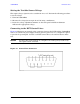
U3025AE10 DUT Control Lines
DUT Control Lines
The 15 pin female D-Sub connector on the rear panel provides 8 latched data connections
that can be used to control your DUT. An adjustable voltage source (+2 to +5 Vdc) is
provided on the front panel. A positive or negative external source can be used. Refer to
Table 8 and Figure 30 on page 31.
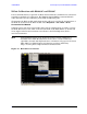
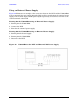
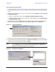
Setting the DUT Control Interface
This section describes how to control the DUT control lines. Refer to “Controlling the
System with E8363/4C and N5230C”. For more information regarding the control lines, see
Table 6 on page 27 and Table 7 on page 28.
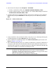
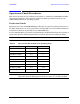
Table 6 Test Set DUT Control Address and Data
Address Data Data
AD12–AD0
Description Bit Data
0= +Voltage
1= –Voltage
112 0 0000000000000 ALL DUT Control Lines set to 0 or + voltage
112 255 0000001111111 ALL DUT Control Lines set to 0 or – voltage
112
1
00000xxxxxxxB DUT Control Line 1 0,1
112
2
00000xxxxxxBx DUT Control Line 2 0,1
112
4
00000xxxxxBxx DUT Control Line 3 0,1
112
8
00000xxxxBxxx DUT Control Line 4 0,1
112
16
00000xxxBxxxx DUT Control Line 5 0,1
112
32
00000xxBxxxxx DUT Control Line 6 0,1
112
64
00000xBxxxxxx DUT Control Line 7 0,1
112
128
00000Bxxxxxxx DUT Control Line 8 0,1
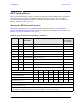
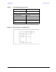
Control Lines Line 8 Line 7 Line 6 Line 5 Line 4 Line 3 Line 2 Line 1
Test Set I/O Bits AD7 AD6 AD5 AD4 AD3 AD2 AD1 AD0
Bit Decimal Equivalent 128 64 32 16 8 4 2 1
Example 1 Data = 0 00000000
Example 2 Data = 21 00010101
X indicates unknown user bit state
B indicates bit of interest
To select a Test Set DUT control line configuration, all 8 DUT control lines must be set. To do this you
must add AD7 to AD0 binary number and convert this to a decimal equivalent.