
User`s guide

14 User’s Guide U3025-90001
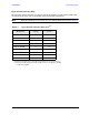
U3025AE10 System Setup E8363C, E8364C or N5230C
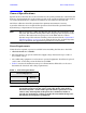
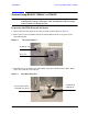
4. Place the network analyzer on top of the Test Set and ensure that the front frame of the
network analyzer is positioned slightly forward of the locks that are attached to the Test
Set. Slide the network analyzer back so the locks engage the front frame of the analyzer.
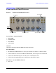
Figure 8 Locking the Analyzer’s
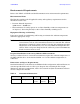
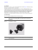
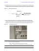
5. Secure the network analyzer’s lower locking feet to the Test Set upper locking feet,
using the spring–loaded screws on the locking feet. Refer to Figure 9. If the network
analyzer's lower locking feet are not aligned with the screw holes in the Test Set's upper
locking feet, loosen the screws securing the feet to the instrument slightly to align.
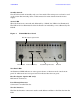
Figure 9 Locking Feet Screws
NOTE There are two Lock-Feet kits available. Refer to “Contacting Agilent” on
page 48 for ordering information.
•PNA − 5023-0132 (Kit includes locking feet and screws)
•Test Set − 5063-9253 (Kit includes lock links, locking feet and screws)
Test Set
Front Frame
Network Analyzer
Front Frame
Slide the network Analyzer
back to engage the lock link
in the back of the network
analyzer's front frame
Lock Link
screw