
User`s guide

User’s Guide U3025-90001 13
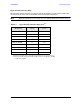
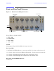
U3025AE10 System Setup E8363C, E8364C or N5230C
System Setup E8363C, E8364C or N5230C
WARNING The opening of covers or removal of parts is likely to expose the user
to dangerous voltages. Disconnect the instrument from all voltage
sources while it is being opened.
Preparing the PNA Network Analyzer
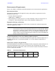
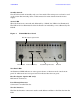
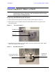
1. Remove the feet from the bottom of the network analyzer. Refer to Figure 6.
2. Remove the 2 lower standoffs and screws (0515-1619) from the rear panel on the
network analyzer.
Figure 6 Rear Bottom Feet
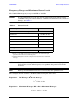
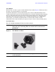
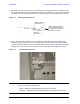
3. Install the two rear locking feet (5023-0132) using the included screws (0515-1619),
where the standoffs were removed.
Figure 7 Install Locking Feet
Standoffs (x2)
Feet (x4)
Locking Feet
(5023-0132)
Included in package
Screws (0515-1619)