Agilent Technologies U3025AE10 User’s Guide Use this manual with the following document: PNA Series Network Analyzer On-line Help System Manufacturing Part Number: U3025-90001 Printed Date: April 7, 2011 Supersede: March 2009 © Copyright 2007-2009, 2011 Agilent Technologies, Inc. All rights reserved.
Warranty Statement THE MATERIAL CONTAINED IN THIS DOCUMENT IS PROVIDED “AS IS,” AND IS SUBJECT TO BEING CHANGED, WITHOUT NOTICE, IN FUTURE EDITIONS. FURTHER, TO THE MAXIMUM EXTENT PERMITTED BY APPLICABLE LAW, AGILENT DISCLAIMS ALL WARRANTIES, EITHER EXPRESS OR IMPLIED WITH REGARD TO THIS MANUAL AND ANY INFORMATION CONTAINED HEREIN, INCLUDING BUT NOT LIMITED TO THE IMPLIED WARRANTIES OF MERCHANTABILITY AND FITNESS FOR A PARTICULAR PURPOSE.
Safety Notes The following safety notes are used throughout this document. Familiarize yourself with each of these notes and its meaning before performing any of the procedures in this document. WARNING Warning denotes a hazard. It calls attention to a procedure which, if not correctly performed or adhered to, could result in injury or loss of life. Do not proceed beyond a warning note until the indicated conditions are fully understood and met. CAUTION Caution denotes a hazard.
iv User’s Guide
Contents U3025AE10 Introduction . . . . . . . . . . . . . . . . . . . . . . . . . . . . . . . . . . . . . . . . . . . . . . . . . . . . . . . . . . . . . . . . . 2 Description . . . . . . . . . . . . . . . . . . . . . . . . . . . . . . . . . . . . . . . . . . . . . . . . . . . . . . . . . . . . . . . . . . 3 Network Analyzer Requirement . . . . . . . . . . . . . . . . . . . . . . . . . . . . . . . . . . . . . . . . . . . . . . . 4 Verifying the Shipment. . . . . . . . . . . . . . . . . . . . . . . . . . .
Contents Service Information . . . . . . . . . . . . . . . . . . . . . . . . . . . . . . . . . . . . . . . . . . . . . . . . . . . . . . . . . .41 Replaceable Parts . . . . . . . . . . . . . . . . . . . . . . . . . . . . . . . . . . . . . . . . . . . . . . . . . . . . . . . . . . .41 Safety and Regulatory Information . . . . . . . . . . . . . . . . . . . . . . . . . . . . . . . . . . . . . . . . . . . . . .42 Introduction . . . . . . . . . . . . . . . . . . . . . . . . . . . . . . . . . . . . . . . . . . .
U3025AE10 User’s Guide U3025-90001 1
U3025AE10 Introduction Introduction This document describes how to use the U3025AE10 Multiport Test Set with the Agilent E8363C and E8364C 2-Port and the N5230C 2-Port PNA Network Analyzer.
U3025AE10 Description Description The Agilent U3025AE10 is a 10-Port mechanical switching extension Test Set (10 MHz to 50 GHz). When combined with a E8363/4C Option 014 or N5230C Option 525 or 425 2-Port network analyzer, the U3025AE10 provides a complete solution for 8-Port full crossbar measurements. The U3025AE10 can be used with the E8363C (10 MHz to 40 GHz). The test ports are 2.4 mm male. The Test Set is controlled by the Test Set I/O connector located on the rear panel of the PNA network analyzer.
U3025AE10 Description Network Analyzer Requirement • All PNA, PNA-L Network Analyzers require Option 551, which adds N-Port error correction and full cross-bar measurement capability. • PNA firmware revision: N5230C and E8363/4C Option 551 ≥ A.08.04.10 • The N5230C PNA-L requires Option 525 or 425 (40 GHz) to provide the Test Set interface connections and requires Test Set file u302xae10_p2.tsx.
U3025AE10 Available Options Available Options Test Set Options The U3025AE10 has two available Test Set options: Refer to “System Block Diagrams” beginning on page 40. • Standard - Includes amplifiers. • Option 001 provides Bias Tee’s for the 10-Ports in the Test Set. Mounting Kits Installation instructions are included in the option package. • Option 1CM - Rackmount Kit (5063-9215). • Option 1CN - Front-Handle Kit (5063-9228). • Option 1CP - Rackmount with front handle Kit (5063-9222).
U3025AE10 General Specifications General Specifications Specifications for the Test Set are characteristic for the system performance of the PNA and Test Set. Actual performance of the system is based on the customer’s PNA and options that are used with the Test Set. A functional certificate is only offered for the Test Set. An N-Port calibration should be performed for optimum measurement accuracy. A periodic calibration is not required.
U3025AE10 General Specifications Environmental Requirements Refer to the PNA-L or PNA-X standard documentation for environmental requirements. Environmental Tests The Test Set complies with all applicable safety and regulatory requirements for the intended location of use. • Pressure Altitude (Operation) 3,000 meters (~10,000 feet) • The instrument can safely operate in a relative humidity of 80% for temperatures to 31 degrees C, decreasing linearly to 50% relative humidity at 40 degrees C.
U3025AE10 General Specifications Frequency Range and Maximum Power Levels The U3025AE10 frequency range is 10 MHz to 50 GHz. CAUTION Table 3 It is recommend that you do not operate components near damage levels (+30 dBm). The power levels must be 3 dB below maximum level to ensure no damage, see Table 3.
U3025AE10 General Specifications Typical Reflection Tracking Specifications for the Test Set are typical. System performance for the PNA and Test Set are only characteristic and are intended as non-warranted information. Typical specifications are based on 1 to 2 units performance, refer to Table 4. NOTE Table 4 Typical Reflection Tracking Loss1, 2 Standard (dB) (typical) Option 001 (dB) (typical) 10 MHz to 45 MHz +3.0 +2.5 45 MHz to 500 MHz +6.5 +6.0 500 MHz to 2 GHz +4.0 +3.
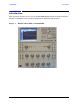
U3025AE10 Front and Rear Panel Features Front and Rear Panel Features Figure 3 Front Panel (Multiport Test Set) Access Ports Access Ports Active LED Standby Switch Test Ports (x10) Test Port LED’s Ground Access Ports - 3.5 mm (female) • CPLR ARM • SOURCE OUT • CPLR THRU • A IN – B IN Ground Chassis ground is provided for ESD and safety connection. Test Port LEDs • An illuminated LED indicates an active port and if it is in Source or Receiver mode.
U3025AE10 Front and Rear Panel Features Standby Switch Note that this switch is Standby only, not a line switch. The main power cord can be used as the system disconnecting device. It disconnects the mains circuits from the mains supply. Active LED When the Test Set is connected and addressed by a PNA-X, the LED is On (illuminated). The LED is Off (not illuminated) when the Test Set is in Standby, or not addressed by the PNA-X.
U3025AE10 Front and Rear Panel Features Line Module The line fuse, as well as a spare, reside within the line module. Figure 5 illustrates where the fuses are located and how to access them. Install the instrument so that the detachable power cord is readily identifiable and is easily reached by the operator. The detachable power cord is the instrument disconnecting device. It disconnects the mains circuits from the mains supply before other parts of the instrument.
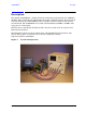
U3025AE10 System Setup E8363C, E8364C or N5230C System Setup E8363C, E8364C or N5230C WARNING The opening of covers or removal of parts is likely to expose the user to dangerous voltages. Disconnect the instrument from all voltage sources while it is being opened. Preparing the PNA Network Analyzer 1. Remove the feet from the bottom of the network analyzer. Refer to Figure 6. 2. Remove the 2 lower standoffs and screws (0515-1619) from the rear panel on the network analyzer.
U3025AE10 System Setup E8363C, E8364C or N5230C 4. Place the network analyzer on top of the Test Set and ensure that the front frame of the network analyzer is positioned slightly forward of the locks that are attached to the Test Set. Slide the network analyzer back so the locks engage the front frame of the analyzer.
U3025AE10 System Setup E8363C, E8364C or N5230C RF Interface Cable Connections Figure 10 illustrates the setup configuration of the U3025AE10 Multiport Test Set and how it should be configured to the E8364C 2-Port and N5230C PNA Network Analyzer. 1. Remove the SOURCE OUT to CPLR THRU and RCVR IN to CPLR ARM jumpers (x8) on the PNA. The RCVR R1 - R2 to SOURCE OUT reference loop jumpers (x2) remain on the front panel. 2.
U3025AE10 System Setup E8363C, E8364C or N5230C 3. Connect the PNA Test Set I/O cable (8120-6818) to the U3025AE10 Test Set Interface on the rear panel.
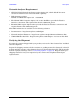
U3025AE10 Controlling the System with E8363/4C and N5230C Controlling the System with E8363/4C and N5230C This section will describe how to setup and operate the U3025AE10 Multiport Test Set with the E8363/4C and N5230C 2-Port PNA Network Analyzer. NOTE The internal firmware of the Agilent E8363/4C and N5230C has not been modified for this Test Set option. Power levels may differ from those indicated on the PNA when the Test Set is connected.
U3025AE10 Controlling the System with E8363/4C and N5230C PNA Multiport Mode for E8363/4C and N5230C with Option 551 The PNA Multiport Mode selects the Test Set file that will enable the PNA to control the Test Set. The PNA Multiport Mode allows you to complete a N-Port calibration using the Cal Wizard application in the PNA. Refer to the PNA Help system for more information. 12-Port System with E8363/4C and N5230C 1. The E8363/4C and N5230C Option 551 must be installed for Multiport capability.
U3025AE10 Controlling the System with E8363/4C and N5230C External Test Set Control Feature To verify that the network application has the U302xAE10 interface features, select Trace/Chan > Channel > Hardware Setup > External Test Set > Other. The Test Set will be displayed as External Test Set Control-U302xAE10. Figure 15 External Test Set Control This menu will allow the physical Ports 1 through 12 to be identified as any port for your convenience. For example; Port 5 can be named Port 2.
U3025AE10 Controlling the System with E8363/4C and N5230C Select the Port Control down arrow for Ports 9 through 12. Figure 17 External Test Set U302xAE10 (Port 9 - 12) Trace Measure S-Parameter S-Parameter selection can be accomplished using Response > Measure. Use the drop-down menus to select 1 of 144 S-Parameters for the 12-Port system. The first number in the Sxx selection is the Receiver Port and the second number will be the Source Port.
U3025AE10 Controlling the System with E8363/4C and N5230C New Trace Measure S-Parameter S-Parameter Tab: Multiple S-Parameters can be made by selecting Trace/Chan > Trace > New Trace. Use the drop-down menu and select of any of the 144 S-Parameter's.
U3025AE10 Figure 21 Controlling the System with E8363/4C and N5230C 12-Port New Trace Measure (S88 - S12_12) Scroll Bar Balanced Tab: Balanced Measurements can be configured by selecting the Balance tab in the New Trace menu. For more information on balanced (differential) component measurement, refer to the Application Note 1373-1 and 1373-2 (5988-5634EN and 5988-5635EN) at http://www.home.agilent.com. In the search menu type in “Multiport and Balanced.
U3025AE10 Controlling the System with E8363/4C and N5230C Receivers Tab: The S-Parameter measurements can be ratioed with selectable Denominators for each port and receiver. Refer to the standard PNA-X documentation for more information.
U3025AE10 Controlling the System with E8363/4C and N5230C Sweep Setup for Multiport and Standalone PNA Modes When the Test Set is connected to the PNA, it is recommended that the analyzer’s Sweep Setup be configured to Stepped Sweep before calibrating. This is slower than the Analog Sweep, but is more accurate due to the extra electrical length of the Test Set and test port cables. Only Stepped Sweep is available on all PNA models. 1. On the PNA select STIMULAS > Sweep > Sweep Setup. 2.
U3025AE10 Controlling the System with E8363/4C and N5230C N-Port Calibration with E8363/4C and N5230C It is recommended that you perform an ECal characterization to minimize the connections required for multiple port calibration. The N4693A Option M0F is recommended with cable (85133F) if you are calibrating at the PNA and Test Set ports. Characterize the ECal module with adapters that will not be used in the measurement of the DUT.
U3025AE10 Controlling the System with E8363/4C and N5230C 1. On the network analyzer select Response > Cal Wizard. a. If using a mechanical cal kit, select SmartCal (Guided Calibration) > Next. b. If using an ECal module, connect the ECal to an available PNA USB port and select Use Electronic Calibration (ECal) > Next. 2. Continue following the Cal Wizard prompts. In the Select Calibration Ports and ECal Module dialog box press Select All, or select the ports you are calibrating and select Next.
U3025AE10 DUT Control Lines DUT Control Lines The 15 pin female D-Sub connector on the rear panel provides 8 latched data connections that can be used to control your DUT. An adjustable voltage source (+2 to +5 Vdc) is provided on the front panel. A positive or negative external source can be used. Refer to Table 8 and Figure 30 on page 31. Setting the DUT Control Interface This section describes how to control the DUT control lines. Refer to “Controlling the System with E8363/4C and N5230C”.
U3025AE10 DUT Control Lines NOTE All DUT control lines must be set with each command sent.
U3025AE10 DUT Control Lines Setting the Variable Source Voltage The output voltage of pin 12 can be varied from +2 to +5 V. Perform the following procedure to set the voltage: 1. Turn On U3025AE10. 2. Measure the voltage between pin 12 and 15 using a multimeter. 3. Rotate the voltage adjustment trimmer on the front panel until the multimeter indicates the appropriate voltage.
U3025AE10 DUT Control Lines Using an External Power Supply Figure 29 illustrates an example of the connection between the DUT and the U3025AE10 with an external dc power supply. Input the High and Low signals from the external power supply to the Positive Input and Negative Input respectively, and connect each line to the control terminal of the DUT. Turning On the U3025AE10 using an External Power Supply. 1. Turning On the U3025AE10. 2. Connect the DUT. 3. Turn On the external power supply.
U3025AE10 Table 8 DUT Control Lines DUT Control Specifications Item Specifications Connector Shape 15–pin female D–Sub Voltage Range: Figure 30 Positive Input 0 to +5 V Negative Input –5 to 0 V Maximum Current 100 mA (in total of each line) Impedance < 10 Ω Range of Variable Voltage +2 to +5 V Block Diagram of DUT Control User’s Guide U3025-90001 31
U3025AE10 Operational Check Procedures Operational Check Procedures This section provides the test calibration procedure to confirm the U3025AE10 and PNA operational performance. The operation verification limits provided ensure that your U3025AE10 and PNA are operating properly. Verification Limits Specifications for the U3025AE10 Multiport Test Set are typical. System performance for the PNA and Test Set are only characteristic and intended as non warranted information.
U3025AE10 Operational Check Procedures Equipment Required The Agilent U3025AE10 requires that the user be familiar with the equipment and components listed in Table 10. This section provides an equipment list and setup of the PNA and Test Set. Table 10 Equipment List Description Qty E8364C 2-Port Network Analyzer (Option 014 or 551) or N5230C 2-Port Network Analyzer (Option 525 or 551) 1 N4693A ECal Module with a female connector, or a 2.4 mm Cal kit (85056B, 85057D, etc.
U3025AE10 Operational Check Procedures 1-Port Calibration Procedure 1. Connect the ECal or the mechanical cal kit to Port 1 or the port you are testing. Torque to 8 in-lb. Refer to Figure 1 on page 2. For more information refer to the system Help menu. 2. Perform a 1-Port Calibration on Port 1. On the PNA, select Response > Cal > Start Cal > Calibration Wizard. a. If using a mechanical cal kit, select SmartCal (Guided Calibration) > Next. b. If using an ECal module, connect the ECal to a PNA USB port.
U3025AE10 Operational Check Procedures 6. Repeat step 1 thru step 5 (1-Port Calibration Procedure) for Ports 2 thru 12. When finished, there should be twelve Cal Sets saved with the titles “999.1” thru “999.12” (12-Port). If you are using an ECal module you can verify the individual port calibration by selecting Response > Cal > More > ECal > ECal Confidence Check. Select Change Measurement and select the test port S-Parameter > Apply > OK. Then select Read Module Data.
U3025AE10 Operational Check Procedures 9. From the Cal Sets drop-down menu, select 999.1 and check Enable. Select the Reflection Tracking(1,1) term in the center drop-down menu and ensure that the Enable and Error Terms are selected. NOTE You may also create a table on the PNA and enter the limit line stimulus and response values. Select Marker/Analysis > Analysis> Limit Test > Limit Test ON and Limit Line ON > Global pass/fail display ON, select Show Table.
U3025AE10 Operational Check Procedures 10.Compare the Reflection Tracking (1,1) trace to the appropriate limits in Table 9 on page 32. This can be done using Limit Lines, select Marker/Analysis > Analysis > Limit Test > Limit Test ON and Limit Line ON > Global pass/fail display ON, select Show Table. The trace should be above the limit. PASS will be displayed on the screen if the limit lines are used. 11.Repeat step 9 and step 10 for Cal Sets “999.1” thru “999.12” (12-Port).
U3025AE10 Troubleshooting Operational Check Failures Troubleshooting Operational Check Failures If your test results fail the Operational Check limits, verify following: 1. Ensure that the Test Set is turned on and connected properly to the PNA. 2. Check all appropriate network analyzer and Test Set connectors for damage, cleanliness, and proper torque. 3. Repeat the relevant 1-Port calibrations using another ECal or mechanical standard. 4.
U3025AE10 Theory of Operation Theory of Operation The following is a description of the operation of the U3025AE10. Reference the U3025AE10 block diagrams shown in Figure 37 on page 40. This section assumes the user has a general understanding of couplers, switches, and network analyzers. RF Switch Components All RF switches are mechanical. The switches select the RF paths from the PNA Source and Receiver through interconnect cables to Test Set port paths 3 through 12.
U3025AE10 Theory of Operation System Block Diagrams Figure 37 Standard Configuration Port 3 R1 Port 5 Port 7 A AIN CPLR ARM SOURCE OUT CPLR THRU Port 9 Port 1 E8364B 2-Port PNA Mechanical Switches Port 4 U3025AE10 Standard Configuration Port 11 Port 2 Port 6 CPLR THRU SOURCE OUT BIN B Port 8 CPLR ARM R2 Port 10 Port 12 40 User’s Guide U3025-90001
U3025AE10 Service Information Service Information Refer to “Contacting Agilent” on page 48. WARNING No operator serviceable parts inside. Refer servicing to qualified personnel. To prevent electrical shock do not remove covers. WARNING These servicing instructions are for use by qualified personnel only. To avoid electrical shock, do not perform any servicing unless you are qualified to do so.
U3025AE10 Safety and Regulatory Information Safety and Regulatory Information Introduction Review this product and related documentation to familiarize yourself with safety markings and instructions before you operate the instrument. The documentation contains information and warnings that must be followed by the user to ensure safe operation and to maintain the product in a safe condition.
U3025AE10 Safety and Regulatory Information Before Applying Power Verify that the premises electrical supply is within the range of the instrument. The instrument has an autoranging power supply. WARNING If this product is not used as specified, the protection provided by the equipment could be impaired. This product must be used in a normal condition (in which all means for protection are intact) only.
U3025AE10 Safety and Regulatory Information Servicing WARNING Danger of explosion if battery is incorrectly replaced. Replace only with the same or equivalent type recommended. Discard used batteries according to manufacturer’s instructions. WARNING These servicing instructions are for use by qualified personnel only. To avoid electrical shock, do not perform any servicing unless you are qualified to do so.
U3025AE10 Electrostatic Discharge Protection Electrostatic Discharge Protection Protection against electrostatic discharge (ESD) is essential while removing assemblies from or connecting cables to the instrument. Static electricity can build up on your body and can easily damage sensitive internal circuit elements when discharged. Static discharges too small to be felt can cause permanent damage.
U3025AE10 Regulatory Information Regulatory Information Instrument Markings This section contains information that is required by various government regulatory agencies. The instruction documentation symbol. The product is marked with this symbol when it is necessary for the user to refer to the instructions in the documentation. This symbol indicates separate collection for electrical and electronic equipment, mandated under EU law as of August 13, 2005.
U3025AE10 Regulatory Information Battery Collection Do not throw batteries away but collect as small chemical waste, or in accordance with your country’s requirements. You may return the battery to Agilent Technologies for disposal. Refer to “Contacting Agilent” on page 48 for assistance. Compliance with German Noise Requirements This is to declare that this instrument is in conformance with the German Regulation on Noise Declaration for Machines (Laermangabe nach der Maschinenlaermrerordnung-3.
U3025AE10 Agilent Support, Services, and Assistance Agilent Support, Services, and Assistance Service and Support Options The standard product warranty is a one-year return to Agilent Technologies service warranty. NOTE There are many other repair and calibration options available from the Agilent Technologies support organization. These options cover a range of service agreements with varying response times. Contact Agilent for additional information on available service agreements for this product.