
User`s guide
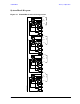
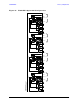

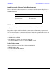
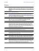
Table Of Contents
- U3042AE12
- Title Page
- TOC
- Introduction
- Description
- Available Options
- Verifying the Shipment
- General Specifications
- Typical Reflection Tracking
- Front and Rear Panel Features
- System Setup with N5230A/C
- Controlling the Test Set with N5230A
- System Setup with N5242A
- Controlling the Test Set with N5242A or N5230C
- DUT Control Lines
- Test Set I/O Interface Commands
- Operational Check
- Troubleshooting Operational Check Failures
- Service Information
- Theory of Operation
- RF Switch Components
- S100 - Source to Ports (1, 5, 9 and 13)
- S200 - Source to Ports (2, 6, 10 and 14)
- S300 - Source to Ports (3, 7, 11 and 15)
- S400 - Source to Ports (4, 8, 12 and 16)
- S101 - Receiver to Ports (1, 5, 9 and 13)
- S201 - Receiver to Ports (2, 6, 10 and 14)
- S301 - Receiver to Ports (3, 7, 11 and 15)
- S401 - Receiver to Ports (4, 8, 12 and 16)
- RF Coupler Components
- System Block Diagram
- Safety and Regulatory Information
- Electrostatic Discharge Protection
- Contacting Agilent

84 User’s Guide
U3042AE12 Theory of Operation
S301 - Receiver to Ports (3, 7, 11 and 15)
Switch 301 provides control of the A Receiver path to PNA Port 3 and ports 7, 11 and 15 to
the Test Set. In the state shown in the block diagram, switch 301 routes the Coupler Arm
from the PNA Port 3 to the A Receiver and all unused Test Set ports (7, 11 and 15) Coupler
Arm paths are terminated.
S401 - Receiver to Ports (4, 8, 12 and 16)
Switch 401 provides control of the B Receiver path to PNA Port 4 and ports 8, 12 and 16 to
the Test Set. In the state shown in the block diagram, switch 401 routes the Coupler Arm
from the PNA Port 4 to the B Receiver and all unused Test Set ports Coupler Arm paths
are terminated.
RF Coupler Components
Test set ports (5 - 16) provide the signal separation of the source and receiver paths. The
test set ports can either stimulate or receive a signal to the DUT.