
User`s guide
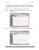
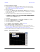
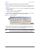

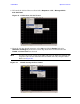
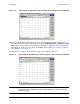
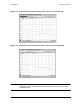

Table Of Contents
- U3042AE12
- Title Page
- TOC
- Introduction
- Description
- Available Options
- Verifying the Shipment
- General Specifications
- Typical Reflection Tracking
- Front and Rear Panel Features
- System Setup with N5230A/C
- Controlling the Test Set with N5230A
- System Setup with N5242A
- Controlling the Test Set with N5242A or N5230C
- DUT Control Lines
- Test Set I/O Interface Commands
- Operational Check
- Troubleshooting Operational Check Failures
- Service Information
- Theory of Operation
- RF Switch Components
- S100 - Source to Ports (1, 5, 9 and 13)
- S200 - Source to Ports (2, 6, 10 and 14)
- S300 - Source to Ports (3, 7, 11 and 15)
- S400 - Source to Ports (4, 8, 12 and 16)
- S101 - Receiver to Ports (1, 5, 9 and 13)
- S201 - Receiver to Ports (2, 6, 10 and 14)
- S301 - Receiver to Ports (3, 7, 11 and 15)
- S401 - Receiver to Ports (4, 8, 12 and 16)
- RF Coupler Components
- System Block Diagram
- Safety and Regulatory Information
- Electrostatic Discharge Protection
- Contacting Agilent
76 User’s Guide
U3042AE12 Operational Check
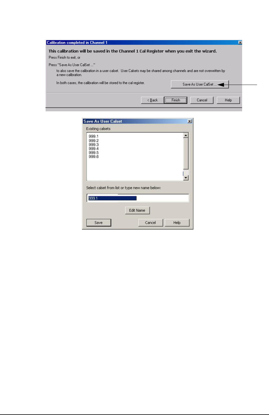
Figure 60 Calibration Complete
6. Repeat step 1 thru step 5 (1-Port Calibration Procedure) for Ports 2 thru 16. When
finished, there should be sixteen Cal Sets saved with the titles “999.1” thru “999.16”
(16-Port).
If you are using an ECal module you can verify the individual port calibration by
selecting Response > CAL > More > ECAL > ECAL Confidence Check. For further
information refer to the system Help menu.
7. Press Trace/Chan > Trace > Delete Trace. There should be no traces on the PNA screen.