
User`s guide
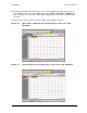

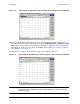
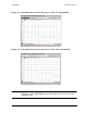

Table Of Contents
- U3042AE12
- Title Page
- TOC
- Introduction
- Description
- Available Options
- Verifying the Shipment
- General Specifications
- Typical Reflection Tracking
- Front and Rear Panel Features
- System Setup with N5230A/C
- Controlling the Test Set with N5230A
- System Setup with N5242A
- Controlling the Test Set with N5242A or N5230C
- DUT Control Lines
- Test Set I/O Interface Commands
- Operational Check
- Troubleshooting Operational Check Failures
- Service Information
- Theory of Operation
- RF Switch Components
- S100 - Source to Ports (1, 5, 9 and 13)
- S200 - Source to Ports (2, 6, 10 and 14)
- S300 - Source to Ports (3, 7, 11 and 15)
- S400 - Source to Ports (4, 8, 12 and 16)
- S101 - Receiver to Ports (1, 5, 9 and 13)
- S201 - Receiver to Ports (2, 6, 10 and 14)
- S301 - Receiver to Ports (3, 7, 11 and 15)
- S401 - Receiver to Ports (4, 8, 12 and 16)
- RF Coupler Components
- System Block Diagram
- Safety and Regulatory Information
- Electrostatic Discharge Protection
- Contacting Agilent
User’s Guide 73
U3042AE12 Operational Check
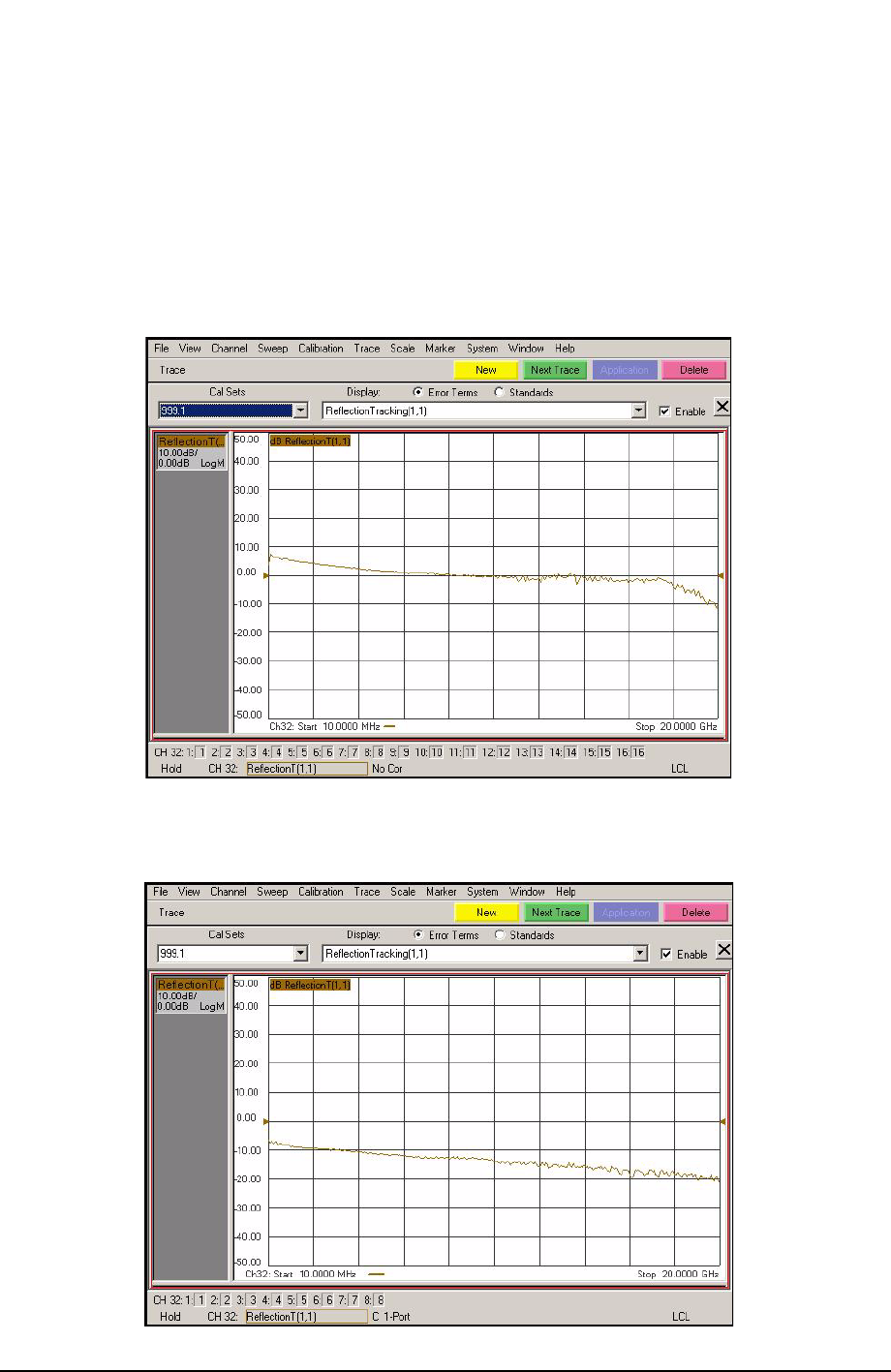
10.Compare the Reflection Tracking (1,1) trace to the appropriate limits in Table 24 on
page 66. This can be done using Limit Lines (press Trace > Limit Test) or Marker. The
trace should be above the limit. PASS will be displayed on the screen if the limit lines
are used.
11.Repeat step 9 and step 10 for Cal Sets “999.1” thru “999.16” (16-Port).
Figure 56 Option 001 or 002 Reflection Tracking Trace (Port 1-16) with
N5230A/C
Figure 57 Standard Reflection Tracking Trace (Port 1-16) with N5230A/C