
User`s guide
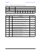
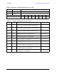
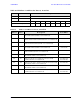


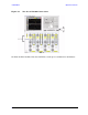
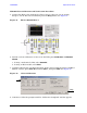
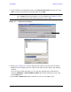
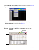
Table Of Contents
- U3042AE12
- Title Page
- TOC
- Introduction
- Description
- Available Options
- Verifying the Shipment
- General Specifications
- Typical Reflection Tracking
- Front and Rear Panel Features
- System Setup with N5230A/C
- Controlling the Test Set with N5230A
- System Setup with N5242A
- Controlling the Test Set with N5242A or N5230C
- DUT Control Lines
- Test Set I/O Interface Commands
- Operational Check
- Troubleshooting Operational Check Failures
- Service Information
- Theory of Operation
- RF Switch Components
- S100 - Source to Ports (1, 5, 9 and 13)
- S200 - Source to Ports (2, 6, 10 and 14)
- S300 - Source to Ports (3, 7, 11 and 15)
- S400 - Source to Ports (4, 8, 12 and 16)
- S101 - Receiver to Ports (1, 5, 9 and 13)
- S201 - Receiver to Ports (2, 6, 10 and 14)
- S301 - Receiver to Ports (3, 7, 11 and 15)
- S401 - Receiver to Ports (4, 8, 12 and 16)
- RF Coupler Components
- System Block Diagram
- Safety and Regulatory Information
- Electrostatic Discharge Protection
- Contacting Agilent
72 User’s Guide
U3042AE12 Operational Check
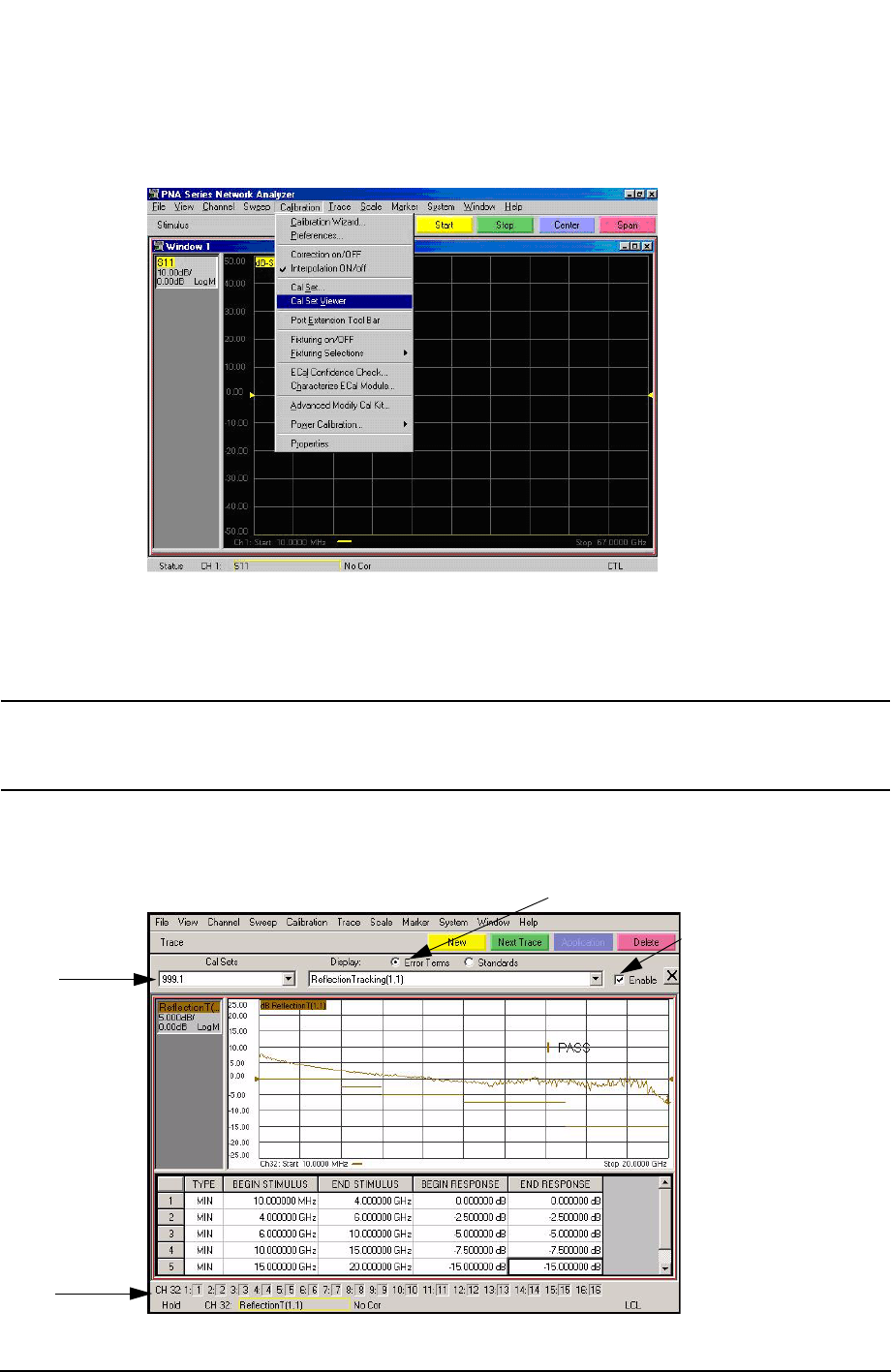
8. Select Calibration > Cal Set Viewer to launch the Cal Set Viewer toolbar. See Figure 54.
Figure 54 Calibration, Cal Set Viewer
9. From the Cal Sets drop-down menu, select 999.1 and check Enable. Select the
Reflection Tracking(1,1) term in the center drop-down menu and ensure that the
Enable and Error Terms are selected as shown in Figure 55.
NOTE You may also create a table on the PNA and enter the limit line stimulus and
response values. Select Limit Test ON and Limit Line ON, and press Show
Table. See Figure 55 on page 72.
Figure 55 Option 001 or 002 Reflection Tracking Trace (Port 1-16) with
N5230A/C
Enable
Error Term
999.1
16-Port