
User`s guide


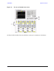
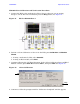
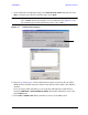
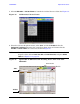
Table Of Contents
- U3042AE12
- Title Page
- TOC
- Introduction
- Description
- Available Options
- Verifying the Shipment
- General Specifications
- Typical Reflection Tracking
- Front and Rear Panel Features
- System Setup with N5230A/C
- Controlling the Test Set with N5230A
- System Setup with N5242A
- Controlling the Test Set with N5242A or N5230C
- DUT Control Lines
- Test Set I/O Interface Commands
- Operational Check
- Troubleshooting Operational Check Failures
- Service Information
- Theory of Operation
- RF Switch Components
- S100 - Source to Ports (1, 5, 9 and 13)
- S200 - Source to Ports (2, 6, 10 and 14)
- S300 - Source to Ports (3, 7, 11 and 15)
- S400 - Source to Ports (4, 8, 12 and 16)
- S101 - Receiver to Ports (1, 5, 9 and 13)
- S201 - Receiver to Ports (2, 6, 10 and 14)
- S301 - Receiver to Ports (3, 7, 11 and 15)
- S401 - Receiver to Ports (4, 8, 12 and 16)
- RF Coupler Components
- System Block Diagram
- Safety and Regulatory Information
- Electrostatic Discharge Protection
- Contacting Agilent
70 User’s Guide
U3042AE12 Operational Check
N5230A 1-Port Calibration and Verification Procedure
1. Connect the ECal or the mechanical cal kit to Port 1 or the port you are testing.
Torque to 8 in-lb. For more information press the Help button, see Figure 51.
Figure 51 ECal at N5230A Port 1
2. Perform a 1-Port Calibration on Port 1. On the PNA, press Calibration > Calibration
Wizard.
a. If using a mechanical cal kit, select SmartCal.
b. If using an ECal module, select ECal.
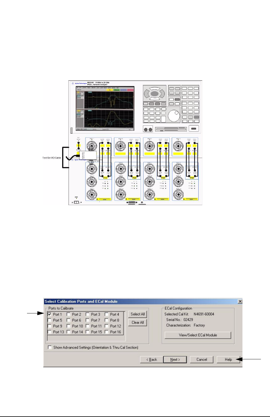
3. Continue following the Cal Wizard prompts. In the “Select Calibration Ports and ECal
Module” window, press Clear All and select Port 1, then press Next. See Figure 52.
Figure 52 1-Port Calibration
4. Continue to follow the prompts until the “Calibration Completed” window appears.
Help