
User`s guide
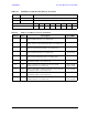
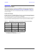


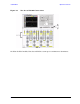
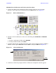
Table Of Contents
- U3042AE12
- Title Page
- TOC
- Introduction
- Description
- Available Options
- Verifying the Shipment
- General Specifications
- Typical Reflection Tracking
- Front and Rear Panel Features
- System Setup with N5230A/C
- Controlling the Test Set with N5230A
- System Setup with N5242A
- Controlling the Test Set with N5242A or N5230C
- DUT Control Lines
- Test Set I/O Interface Commands
- Operational Check
- Troubleshooting Operational Check Failures
- Service Information
- Theory of Operation
- RF Switch Components
- S100 - Source to Ports (1, 5, 9 and 13)
- S200 - Source to Ports (2, 6, 10 and 14)
- S300 - Source to Ports (3, 7, 11 and 15)
- S400 - Source to Ports (4, 8, 12 and 16)
- S101 - Receiver to Ports (1, 5, 9 and 13)
- S201 - Receiver to Ports (2, 6, 10 and 14)
- S301 - Receiver to Ports (3, 7, 11 and 15)
- S401 - Receiver to Ports (4, 8, 12 and 16)
- RF Coupler Components
- System Block Diagram
- Safety and Regulatory Information
- Electrostatic Discharge Protection
- Contacting Agilent
66 User’s Guide
U3042AE12 Operational Check
Operational Check
This operational check is to confirm the U3042AE12 and PNA operational performance.
The operation verification limits provided ensure that your U3042AE12 and PNA are
operating properly. Refer to “Troubleshooting Operational Check Failures” on page 80 to
ensure the RF interface cables are installed and working correctly before returning the
test set for repairs.
Verification Limits
Specifications for the U3042AE12 Multiport Test Set are typical. System performance for
the PNA and Test Set are only characteristic and intended as non warranted information.
Only a functional certificate is provided for the U3042AE12.
It is recommended that you return your instrument to Agilent Technologies for servicing or
repair if the Test Set and PNA performance exceed the operational verification limits.
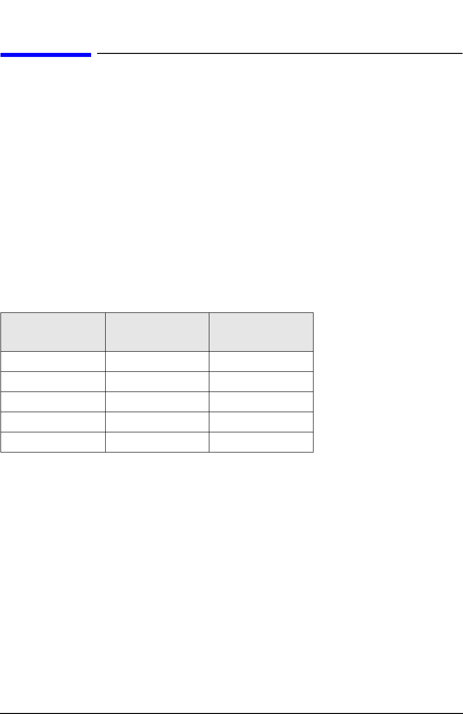
Table 24 N5230A/C Operation Verification Limit for Reflection Tracking
1
1. Reflection Tracking takes into account Source Loss, Receiver
Loss, Margin, and PNA Mixer Cal.
Frequency
Standard
Port 1-16
2
2. A standard unit is one without Options 001 or 002.
Option 001 or 002
Port 1-16
10 MHz to 4 GHz −10.0 dB 0 dB
4 GHz to 6 GHz −13.0 dB −2.5 dB
6 GHz to 10 GHz −16.0 dB −5.0 dB
10 GHz to 15 GHz −17.0 dB −7.5 dB
15 GHz to 20 GHz −25.0 dB −15.0 dB