
User`s guide
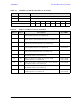
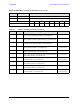
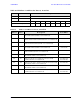


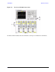
Table Of Contents
- U3042AE12
- Title Page
- TOC
- Introduction
- Description
- Available Options
- Verifying the Shipment
- General Specifications
- Typical Reflection Tracking
- Front and Rear Panel Features
- System Setup with N5230A/C
- Controlling the Test Set with N5230A
- System Setup with N5242A
- Controlling the Test Set with N5242A or N5230C
- DUT Control Lines
- Test Set I/O Interface Commands
- Operational Check
- Troubleshooting Operational Check Failures
- Service Information
- Theory of Operation
- RF Switch Components
- S100 - Source to Ports (1, 5, 9 and 13)
- S200 - Source to Ports (2, 6, 10 and 14)
- S300 - Source to Ports (3, 7, 11 and 15)
- S400 - Source to Ports (4, 8, 12 and 16)
- S101 - Receiver to Ports (1, 5, 9 and 13)
- S201 - Receiver to Ports (2, 6, 10 and 14)
- S301 - Receiver to Ports (3, 7, 11 and 15)
- S401 - Receiver to Ports (4, 8, 12 and 16)
- RF Coupler Components
- System Block Diagram
- Safety and Regulatory Information
- Electrostatic Discharge Protection
- Contacting Agilent
User’s Guide 65
U3042AE12 Test Set I/O Interface Commands
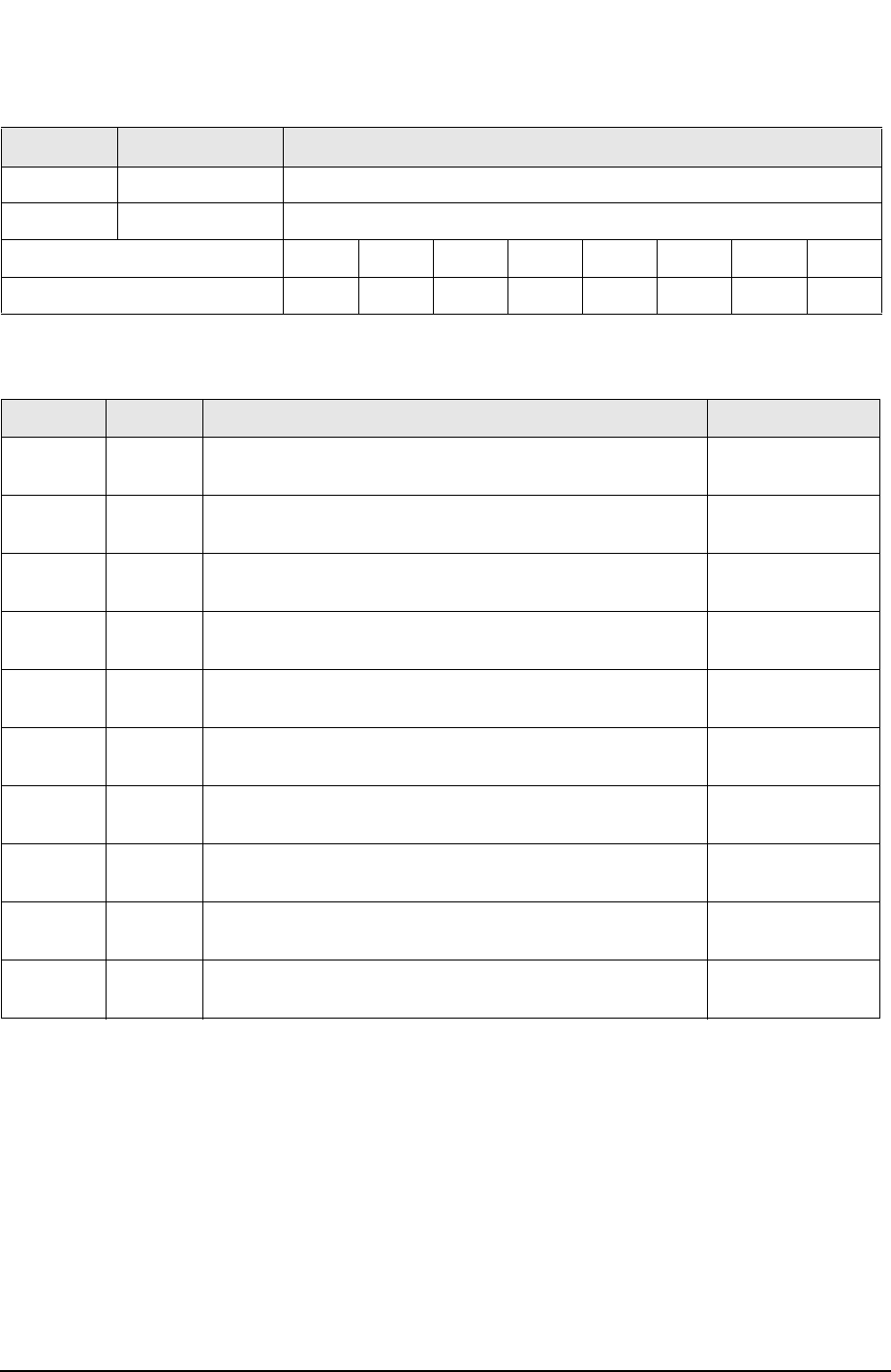
Table 22 PNA Port 1 and Test Set Ports 8, 12 and 16
Address Decimal Data Description
64 D0 - D3 Controls SW400; Source to PNA Port 4 or Test Set Port 8 12 and 16.
64 D4 - D7 Controls SW401; Receiver to PNA Port 4 or Test Set Port 8 12 and 16.
Test Set I/O Data Bits D0 D1 D2 D3 D4 D5 D6 D7
Data Bit Decimal Equivalent 1248163264128
Table 23 Address and Data for Port 8, 12 and 16
Address Data Description Port LED’s
64 17 Selects the Port 4 as the Source and Receiver port. Port 8,
12 and 16 terminated with a 50 Ω switch load.
All Off
64 18 Selects the PNA Port 4 as the Receiver and Port 8 as the
Source. Ports 12 and 16 terminated with a 50 Ω switch load.
Port 8 S ON
64 35 Selects the Port 4 as the Source Port. Port 5 as the Receiver.
Ports 12 and 16 terminated with a 50 Ω switch load.
Port 8 R ON
64 34 Selects the Port 8 as the Source and Receiver port. Port 4,
12 and 16 terminated with a 50 Ω switch load.
Port 8 R ON
Port 8 S ON
64 65 Port 4 as the Source and Port 12 as the Receiver Port. Port 8
and 16 terminated with a 50 Ω switch load.
Port 12 R ON
64 20 Port 4 as the Receiver and Port 12 as the Source. Port 8 and
16 terminated with a 50 Ω switch load.
Port 12 S ON
64 68 Port 12 as the Receiver and Source. Port 4, 8 and 16
terminated with a 50 Ω switch load.
Port 12 R ON
Port 12 S ON
64 24 Port 16 as the Source and Port 4 as the Receiver. Port 8 and
12 terminated with a 50 Ω switch load.
Port 16 S ON
64 129 Port 4 as the Source and Port 16 as the Receiver. Port 8 and
12 terminated with a 50 Ω switch load.
Port 16 R ON
64 68 Port 16 as the Receiver and Source. Port 4, 8 and 12
terminated with a 50 Ω switch load.
Port 16 R ON
Port 16 S ON