
User`s guide
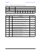
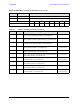
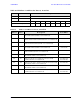


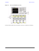
Table Of Contents
- U3042AE12
- Title Page
- TOC
- Introduction
- Description
- Available Options
- Verifying the Shipment
- General Specifications
- Typical Reflection Tracking
- Front and Rear Panel Features
- System Setup with N5230A/C
- Controlling the Test Set with N5230A
- System Setup with N5242A
- Controlling the Test Set with N5242A or N5230C
- DUT Control Lines
- Test Set I/O Interface Commands
- Operational Check
- Troubleshooting Operational Check Failures
- Service Information
- Theory of Operation
- RF Switch Components
- S100 - Source to Ports (1, 5, 9 and 13)
- S200 - Source to Ports (2, 6, 10 and 14)
- S300 - Source to Ports (3, 7, 11 and 15)
- S400 - Source to Ports (4, 8, 12 and 16)
- S101 - Receiver to Ports (1, 5, 9 and 13)
- S201 - Receiver to Ports (2, 6, 10 and 14)
- S301 - Receiver to Ports (3, 7, 11 and 15)
- S401 - Receiver to Ports (4, 8, 12 and 16)
- RF Coupler Components
- System Block Diagram
- Safety and Regulatory Information
- Electrostatic Discharge Protection
- Contacting Agilent
64 User’s Guide
U3042AE12 Test Set I/O Interface Commands
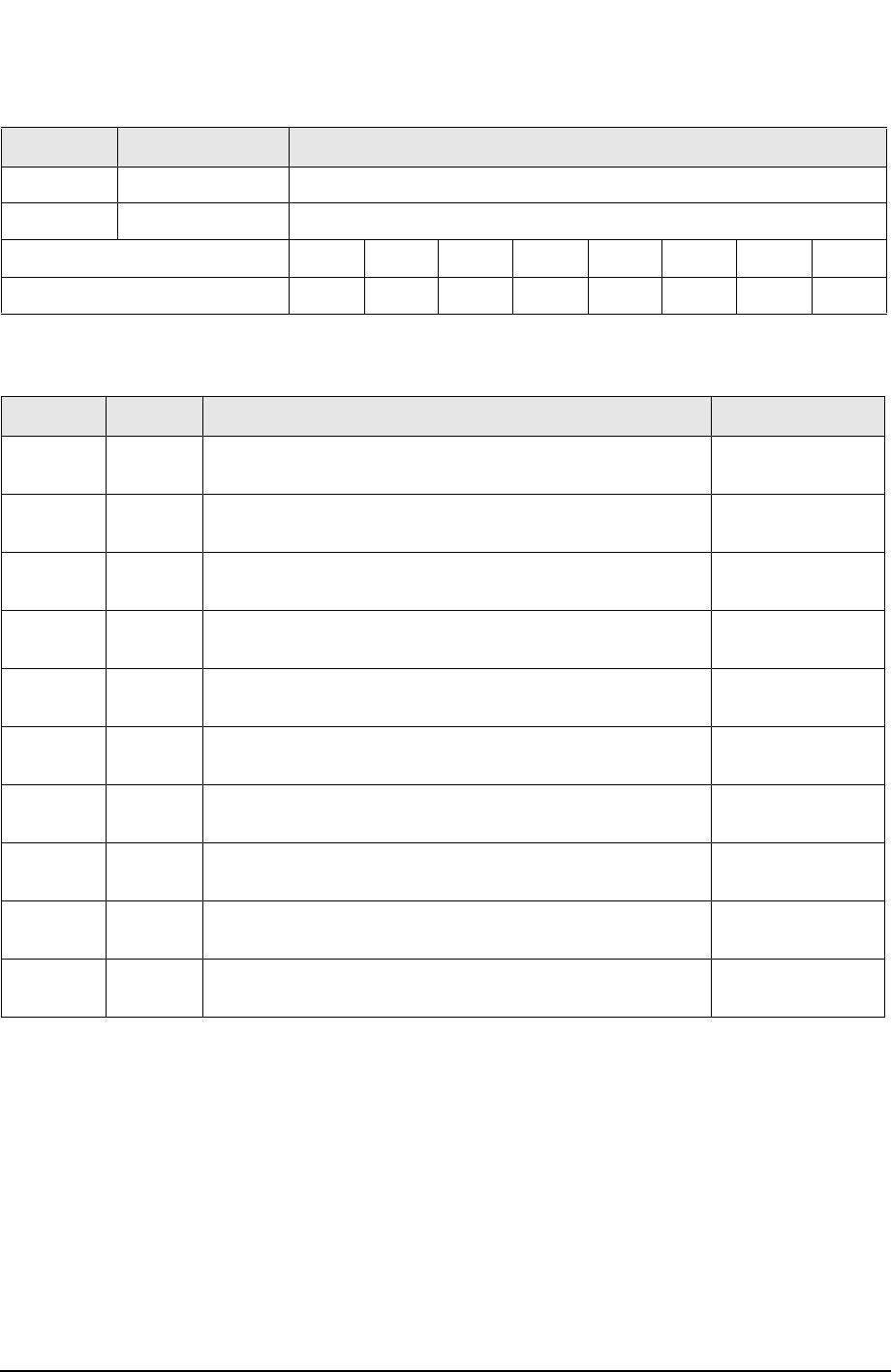
Table 20 PNA Port 1 and Test Set Ports 7, 11 and 15
Address Decimal Data Description
32 D0 - D3 Controls SW300; Source to PNA Port 3 or Test Set Port 7, 11 and 15.
32 D4 - D7 Controls SW301; Receiver to PNA Port 3 or Test Set Port 7, 11 and 15.
Test Set I/O Data Bits D0 D1 D2 D3 D4 D5 D6 D7
Data Bit Decimal Equivalent 1 2 4 8 16 32 64 128
Table 21 Address and Data for Port 7, 11 and 15
Address Data Description Port LED’s
32 17 Selects the Port 3 as the Source and Receiver port.
Port 7, 11 and 15 terminated with a 50 Ω switch load.
All Off
32 18 Selects the PNA Port 3 as the Receiver and Port 7 as the
Source. Ports 11 and 15 terminated with a 50 Ω switch load.
Port 7 S ON
32 35 Selects the Port 3 as the Source Port. Port 7 as the Receiver.
Ports 11 and 15 terminated with a 50 Ω switch load.
Port 7 R ON
32 34 Selects the Port 7 as the Source and Receiver port. Port 3, 11
and 15 terminated with a 50 Ω switch load.
Port 7 R ON
Port 7 S ON
32 65 Port 3 as the Source and Port 11 as the Receiver Port. Port 7
and 15 terminated with a 50 Ω switch load.
Port 11 R ON
32 20 Port 3 as the Receiver and Port 11 as the Source. Port 7 and
15 terminated with a 50 Ω switch load.
Port 11 S ON
32 68 Port 11 as the Receiver and Source. Port 3, 7 and 15
terminated with a 50 Ω switch load.
Port 11 R ON
Port 11 S ON
32 24 Port 15 as the Source and Port 3 as the Receiver. Port 7 and
11 terminated with a 50 Ω switch load.
Port 15 S ON
32 129 Port 3 as the Source and Port 15 as the Receiver. Port 7 and
11 terminated with a 50 Ω switch load.
Port 15 R ON
32 68 Port 15 as the Receiver and Source. Port 3, 7 and 11
terminated with a 50 Ω switch load.
Port 15 R ON
Port 15 S ON