
User`s guide
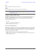
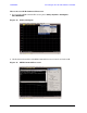

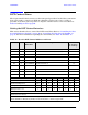
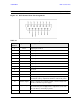
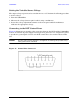

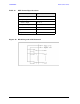

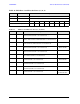
Table Of Contents
- U3042AE12
- Title Page
- TOC
- Introduction
- Description
- Available Options
- Verifying the Shipment
- General Specifications
- Typical Reflection Tracking
- Front and Rear Panel Features
- System Setup with N5230A/C
- Controlling the Test Set with N5230A
- System Setup with N5242A
- Controlling the Test Set with N5242A or N5230C
- DUT Control Lines
- Test Set I/O Interface Commands
- Operational Check
- Troubleshooting Operational Check Failures
- Service Information
- Theory of Operation
- RF Switch Components
- S100 - Source to Ports (1, 5, 9 and 13)
- S200 - Source to Ports (2, 6, 10 and 14)
- S300 - Source to Ports (3, 7, 11 and 15)
- S400 - Source to Ports (4, 8, 12 and 16)
- S101 - Receiver to Ports (1, 5, 9 and 13)
- S201 - Receiver to Ports (2, 6, 10 and 14)
- S301 - Receiver to Ports (3, 7, 11 and 15)
- S401 - Receiver to Ports (4, 8, 12 and 16)
- RF Coupler Components
- System Block Diagram
- Safety and Regulatory Information
- Electrostatic Discharge Protection
- Contacting Agilent
User’s Guide 61
U3042AE12 Test Set I/O Interface Commands
Test Set I/O Interface Commands
Switch Address and Data
Table 16 through Table 23 contain the information to set the internal switch paths of the
U3042AE12 Test Set. Additional information regarding the operation and descriptions for
the internal switches can be found in “Theory of Operation” on page 83.
The address is the first value in the Test Set I/O control or GPIB data command. The
second value controls the source and receiver paths of the ports. To select a test set port
configuration both switches must be set to complete the source and receiver paths. To do
this you must add the decimal values together to determine the data command value,
which is the second number in the test set I/O or GPIB command. Refer Table 15.
Table 16 and Table 17 on page 62 illustrates Port 1, 5, 9 or 13 as the configured source and
receiver paths. Refer to Table 15 to calculate other path combinations.
Example:
If Port 5 is to be the source and Port 6 is to be the receiver.
then;
Source Port 5 = address 0, decimal 2 and Receiver Port 6 = address 16, decimal 32. See
Table 15. Refer to “How to Access Interface Control Settings with N5230A” on page 29 and
in “How to Access GPIB Command Processor with N5230A” on page 33.
Table 15 Port Value Select
Address
Source Path
1
1. All Source switches are 100, 200, 300, and 400.
Receiver Path
2
2. All Receiver switches are 101, 201, 301, and 401.
Bit 01234567
Decimal1248163264128
0 Ports 1591315913
16 Ports 2 610142 61014
32 Ports 3 711153 71115
64 Ports 4 812164 81216