
User`s guide
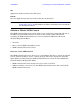
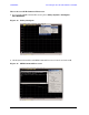

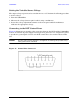


Table Of Contents
- U3042AE12
- Title Page
- TOC
- Introduction
- Description
- Available Options
- Verifying the Shipment
- General Specifications
- Typical Reflection Tracking
- Front and Rear Panel Features
- System Setup with N5230A/C
- Controlling the Test Set with N5230A
- System Setup with N5242A
- Controlling the Test Set with N5242A or N5230C
- DUT Control Lines
- Test Set I/O Interface Commands
- Operational Check
- Troubleshooting Operational Check Failures
- Service Information
- Theory of Operation
- RF Switch Components
- S100 - Source to Ports (1, 5, 9 and 13)
- S200 - Source to Ports (2, 6, 10 and 14)
- S300 - Source to Ports (3, 7, 11 and 15)
- S400 - Source to Ports (4, 8, 12 and 16)
- S101 - Receiver to Ports (1, 5, 9 and 13)
- S201 - Receiver to Ports (2, 6, 10 and 14)
- S301 - Receiver to Ports (3, 7, 11 and 15)
- S401 - Receiver to Ports (4, 8, 12 and 16)
- RF Coupler Components
- System Block Diagram
- Safety and Regulatory Information
- Electrostatic Discharge Protection
- Contacting Agilent
58 User’s Guide
U3042AE12 DUT Control Lines
Setting the Variable Source Voltage
The output voltage of pin 12 can be varied from +2 to +5 V. Perform the following procedure
to set the voltage:
1. Turn On U3042AE12.
2. Measure the voltage between pin 12 and 15 using a multimeter.
3. Rotate the voltage adjustment trimmer on the front panel until the multimeter
indicates the appropriate voltage.
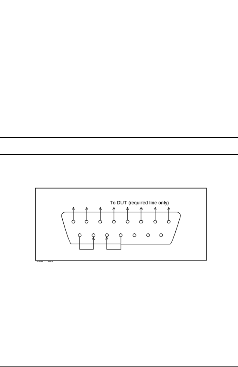
Connecting to the DUT Control Lines
Figure 47 illustrates an example of the connection between the DUT and the U3042AE12
without an external dc power supply. Connect pin 12 to pin 13 for +5 V, and pin 14 to pin 15
to provide the ground path. Connect each DUT control line to the external device under
test.
CAUTION You may only connect pin 12–13, and pin 14–15. Damage may result if any
other path is short–circuited.
Figure 47 Control Line Connector