
User`s guide
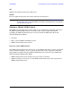
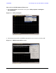

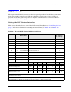
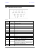
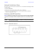

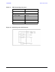

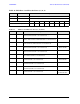
Table Of Contents
- U3042AE12
- Title Page
- TOC
- Introduction
- Description
- Available Options
- Verifying the Shipment
- General Specifications
- Typical Reflection Tracking
- Front and Rear Panel Features
- System Setup with N5230A/C
- Controlling the Test Set with N5230A
- System Setup with N5242A
- Controlling the Test Set with N5242A or N5230C
- DUT Control Lines
- Test Set I/O Interface Commands
- Operational Check
- Troubleshooting Operational Check Failures
- Service Information
- Theory of Operation
- RF Switch Components
- S100 - Source to Ports (1, 5, 9 and 13)
- S200 - Source to Ports (2, 6, 10 and 14)
- S300 - Source to Ports (3, 7, 11 and 15)
- S400 - Source to Ports (4, 8, 12 and 16)
- S101 - Receiver to Ports (1, 5, 9 and 13)
- S201 - Receiver to Ports (2, 6, 10 and 14)
- S301 - Receiver to Ports (3, 7, 11 and 15)
- S401 - Receiver to Ports (4, 8, 12 and 16)
- RF Coupler Components
- System Block Diagram
- Safety and Regulatory Information
- Electrostatic Discharge Protection
- Contacting Agilent
User’s Guide 57
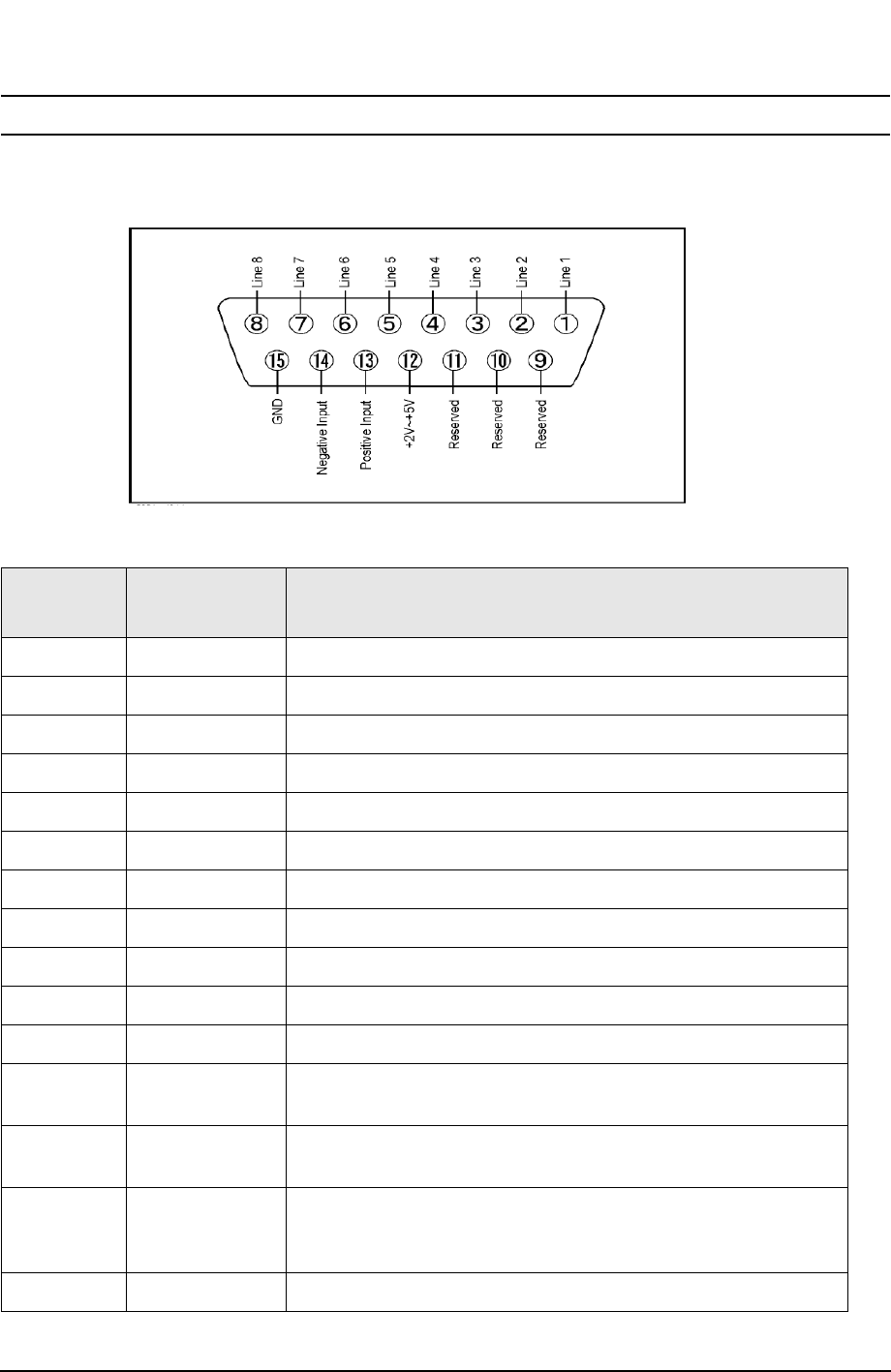
U3042AE12 DUT Control Lines
NOTE All DUT control lines must be set with each command sent. Logic 0 = high
Figure 46 DUT Control Line Pin Assignment
Table 13 DUT Control Line Pin Assignment
Pin
Number
Signal Name Description
1 Line 1 Output port of line 1
2 Line 2 Output port of line 2
3 Line 3 Output port of line 3
4 Line 4 Output port of line 4
5 Line 5 Output port of line 5
6 Line 6 Output port of line 6
7 Line 7 Output port of line 7
8 Line 8 Output port of line 8
9 Not used
10 Not used
11 Not used
12 +2 V to +5 V The voltage input to pin 13. (The voltage can be varied by
rotating the voltage adjustment trimmer on the front panel).
13 Positive Input Input a signal that is outputted when each line is high from
pin 12 or external dc power supply.
14 Negative Input Input a signal that is outputted when each line is low from
the external dc power supply. Able to output 0 V as low from
the each line by connecting to pin 15.
15 Gnd ground terminal