
User`s guide

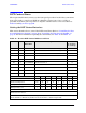
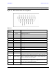
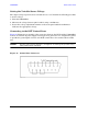

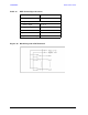

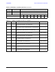
Table Of Contents
- U3042AE12
- Title Page
- TOC
- Introduction
- Description
- Available Options
- Verifying the Shipment
- General Specifications
- Typical Reflection Tracking
- Front and Rear Panel Features
- System Setup with N5230A/C
- Controlling the Test Set with N5230A
- System Setup with N5242A
- Controlling the Test Set with N5242A or N5230C
- DUT Control Lines
- Test Set I/O Interface Commands
- Operational Check
- Troubleshooting Operational Check Failures
- Service Information
- Theory of Operation
- RF Switch Components
- S100 - Source to Ports (1, 5, 9 and 13)
- S200 - Source to Ports (2, 6, 10 and 14)
- S300 - Source to Ports (3, 7, 11 and 15)
- S400 - Source to Ports (4, 8, 12 and 16)
- S101 - Receiver to Ports (1, 5, 9 and 13)
- S201 - Receiver to Ports (2, 6, 10 and 14)
- S301 - Receiver to Ports (3, 7, 11 and 15)
- S401 - Receiver to Ports (4, 8, 12 and 16)
- RF Coupler Components
- System Block Diagram
- Safety and Regulatory Information
- Electrostatic Discharge Protection
- Contacting Agilent
56 User’s Guide
U3042AE12 DUT Control Lines
DUT Control Lines
The 15 pin female D-Sub connector on the front panel provides 8 latched data connections
that can be used to control your DUT. An adjustable voltage source (+2 to +5 Vdc) is
provided on the front panel. A positive or negative external source can be used. Refer to
Table 14 and Figure 49 on page 60.
Setting the DUT Control Interface
This section describes how to control the DUT control lines. Refer to “Controlling the Test
Set with N5242A or N5230C” on page 40 or “Controlling the Test Set with N5230A” on
page 17. For more information regarding the control lines, see Table 12 and Table 13.
Table 12 Test Set DUT Control Address and Data
Address Data Data
AD12–AD0
Description Bit Data
0= +Voltage
1= –Voltage
112 0 0000000000000 ALL DUT Control Lines set to 0 or + voltage
112 255 0000001111111 ALL DUT Control Lines set to 0 or – voltage
112
1
00000xxxxxxxB DUT Control Line 1 0,1
112
2
00000xxxxxxBx DUT Control Line 2 0,1
112
4
00000xxxxxBxx DUT Control Line 3 0,1
112
8
00000xxxxBxxx DUT Control Line 4 0,1
112
16
00000xxxBxxxx DUT Control Line 5 0,1
112
32
00000xxBxxxxx DUT Control Line 6 0,1
112
64
00000xBxxxxxx DUT Control Line 7 0,1
112
128
00000Bxxxxxxx DUT Control Line 8 0,1
Control Lines Line 8 Line 7 Line 6 Line 5 Line 4 Line 3 Line 2 Line 1
Test Set I/O Bits AD7 AD6 AD5 AD4 AD3 AD2 AD1 AD0
Bit Decimal Equivalent 128 64 32 16 8 4 2 1
Example 1 Data = 0 00000000
Example 2 Data = 21 00010101
X indicates unknown user bit state
B indicates bit of interest
To select a test set DUT control line configuration, all 8 DUT control lines must be set. To do this you
must add AD7 to AD0 binary number and convert this to a decimal equivalent.