
User`s guide
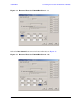
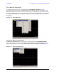
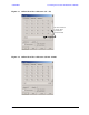

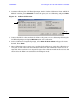

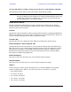
Table Of Contents
- U3042AE12
- Title Page
- TOC
- Introduction
- Description
- Available Options
- Verifying the Shipment
- General Specifications
- Typical Reflection Tracking
- Front and Rear Panel Features
- System Setup with N5230A/C
- Controlling the Test Set with N5230A
- System Setup with N5242A
- Controlling the Test Set with N5242A or N5230C
- DUT Control Lines
- Test Set I/O Interface Commands
- Operational Check
- Troubleshooting Operational Check Failures
- Service Information
- Theory of Operation
- RF Switch Components
- S100 - Source to Ports (1, 5, 9 and 13)
- S200 - Source to Ports (2, 6, 10 and 14)
- S300 - Source to Ports (3, 7, 11 and 15)
- S400 - Source to Ports (4, 8, 12 and 16)
- S101 - Receiver to Ports (1, 5, 9 and 13)
- S201 - Receiver to Ports (2, 6, 10 and 14)
- S301 - Receiver to Ports (3, 7, 11 and 15)
- S401 - Receiver to Ports (4, 8, 12 and 16)
- RF Coupler Components
- System Block Diagram
- Safety and Regulatory Information
- Electrostatic Discharge Protection
- Contacting Agilent
50 User’s Guide
U3042AE12 Controlling the Test Set with N5242A or N5230C
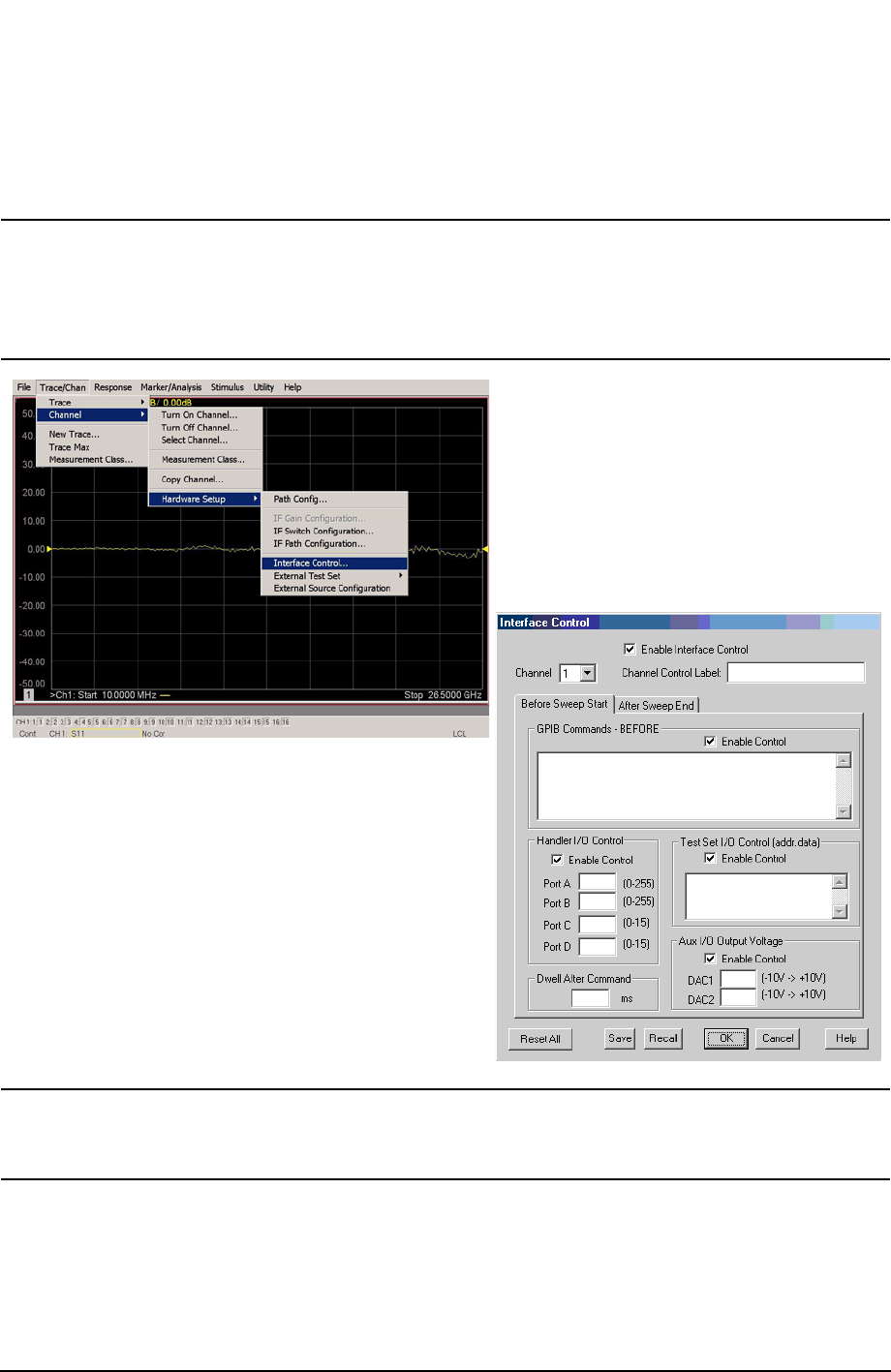
How to Access Interface Control Settings
This section will describe how to setup and operate the U3042AE12 Multiport Test Set
with the PNA-X. To access the Interface Control application select Trace/Chan > Channel >
Hardware Setup > Interface Control in the drop-down menu.
NOTE The PNA-X Series Network Analyzer comes with the Interface Control
application. Please review this application before connecting the U3042AE12
Test Set to the PNA. Information regarding this application can be found in
the PNA’s Help System Menu, InterfaceControl. The application is shown
below.
NOTE While using Interface Control, the PNA-X must be in GPIB System Controller
mode. Once this is complete you must restart the PNA application to go back
to Talker/Listener.