
User`s guide
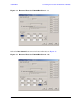
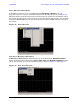
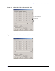
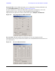

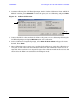

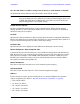
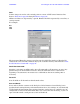
Table Of Contents
- U3042AE12
- Title Page
- TOC
- Introduction
- Description
- Available Options
- Verifying the Shipment
- General Specifications
- Typical Reflection Tracking
- Front and Rear Panel Features
- System Setup with N5230A/C
- Controlling the Test Set with N5230A
- System Setup with N5242A
- Controlling the Test Set with N5242A or N5230C
- DUT Control Lines
- Test Set I/O Interface Commands
- Operational Check
- Troubleshooting Operational Check Failures
- Service Information
- Theory of Operation
- RF Switch Components
- S100 - Source to Ports (1, 5, 9 and 13)
- S200 - Source to Ports (2, 6, 10 and 14)
- S300 - Source to Ports (3, 7, 11 and 15)
- S400 - Source to Ports (4, 8, 12 and 16)
- S101 - Receiver to Ports (1, 5, 9 and 13)
- S201 - Receiver to Ports (2, 6, 10 and 14)
- S301 - Receiver to Ports (3, 7, 11 and 15)
- S401 - Receiver to Ports (4, 8, 12 and 16)
- RF Coupler Components
- System Block Diagram
- Safety and Regulatory Information
- Electrostatic Discharge Protection
- Contacting Agilent

User’s Guide 49
U3042AE12 Controlling the Test Set with N5242A or N5230C
N5242A or N5230C Interface Control
NOTE The interface control will not function properly when using the mutliport
mode. The multiport mode will reset the switch path commands of the
interface control. It is recommended that the PNA be restarted in stand-alone
mode if the interface control is being used.
This section includes only the features required in the Interface Control for the
U3042AE12 Multiport Test Set. Applications and feature information can be found in the
PNA’s Help System Menu, “Interface Control.”
•Overview
• How to Access Interface Control Settings
• Interface Control Dialog Box
Other connectivity topics can be found in the PNA Series Network Analyzer’s Help System
Menu.
Overview of the Interface Control
The Interface Control feature allows you to send data and remote commands to control
external equipment using the GPIB, Material Handler I/O, Test Set I/O, and Auxiliary I/O
without needing to create a remote program. Refer to PNA Series Network Analyzer’s Help
System Menu, “Rear Panel Tour.”
• A unique set of control data can be sent for each channel. In addition, a unique set of
control data can be sent before the channel sweep starts and after the sweep ends.
• Interface Control settings can be saved and recalled from the Interface Control Dialog
Box or with Instrument State Save and Recall.
• Interface Control settings can be copied to other channels using Copy Channels.
• Control data can only be WRITTEN to the interfaces, NOT READ from the interfaces.
• Control data is sent in the following order and this order cannot be changed:
1. GPIB Interface
2. Material Handler Interface (not covered in this manual)
3. Test Set Interface (not covered in this manual)
4. Dwell Time (not covered in this manual)