
User`s guide
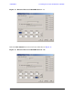
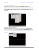
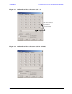
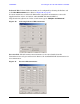

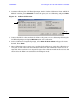

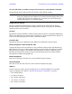
Table Of Contents
- U3042AE12
- Title Page
- TOC
- Introduction
- Description
- Available Options
- Verifying the Shipment
- General Specifications
- Typical Reflection Tracking
- Front and Rear Panel Features
- System Setup with N5230A/C
- Controlling the Test Set with N5230A
- System Setup with N5242A
- Controlling the Test Set with N5242A or N5230C
- DUT Control Lines
- Test Set I/O Interface Commands
- Operational Check
- Troubleshooting Operational Check Failures
- Service Information
- Theory of Operation
- RF Switch Components
- S100 - Source to Ports (1, 5, 9 and 13)
- S200 - Source to Ports (2, 6, 10 and 14)
- S300 - Source to Ports (3, 7, 11 and 15)
- S400 - Source to Ports (4, 8, 12 and 16)
- S101 - Receiver to Ports (1, 5, 9 and 13)
- S201 - Receiver to Ports (2, 6, 10 and 14)
- S301 - Receiver to Ports (3, 7, 11 and 15)
- S401 - Receiver to Ports (4, 8, 12 and 16)
- RF Coupler Components
- System Block Diagram
- Safety and Regulatory Information
- Electrostatic Discharge Protection
- Contacting Agilent
48 User’s Guide
U3042AE12 Controlling the Test Set with N5242A or N5230C
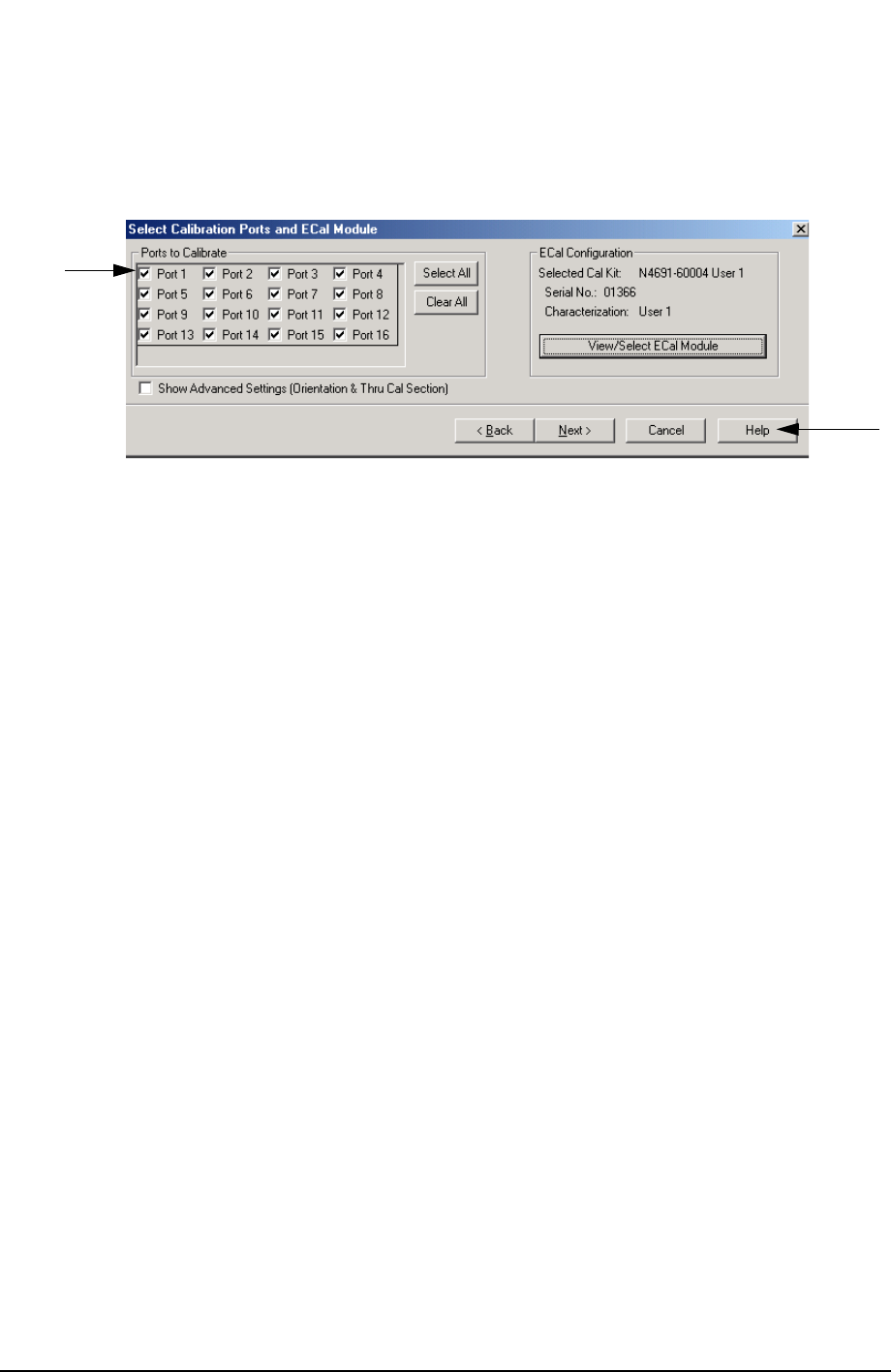
2. Continue following the Cal Wizard prompts. On the “Select Calibration Ports and ECal
Module” window, press Select All or select the ports you are calibrating and press Next.
Figure 43 16-Port Calibration
3. Connect the ECal or the mechanical cal kit to the ports you are calibrating following the
Cal Wizard prompts and press Measure after each connection.
4. At the Calibration Completed prompt, select Save As User Calset and type the name
desired. Press Save.
5. After calibrating test set ports, use a quality load and short to verify the calibration on
each port or end of the test cable. Measure reflection and confirm the return loss is as
expected. If the result is not as expected, repeat the calibration without the test set and
ensure that the PNA is in standard (non-multiport) mode.
Help